Waterproofing and Tanking
BS 8102 Types A, B and C, roof membranes and wet-area tanking — keeping water out, or accepting it and managing it, without kidding yourself about which one you are doing.
Last updated 2026-07-28 by the BuildPedia Editorial Team.
What is Waterproofing and Tanking?
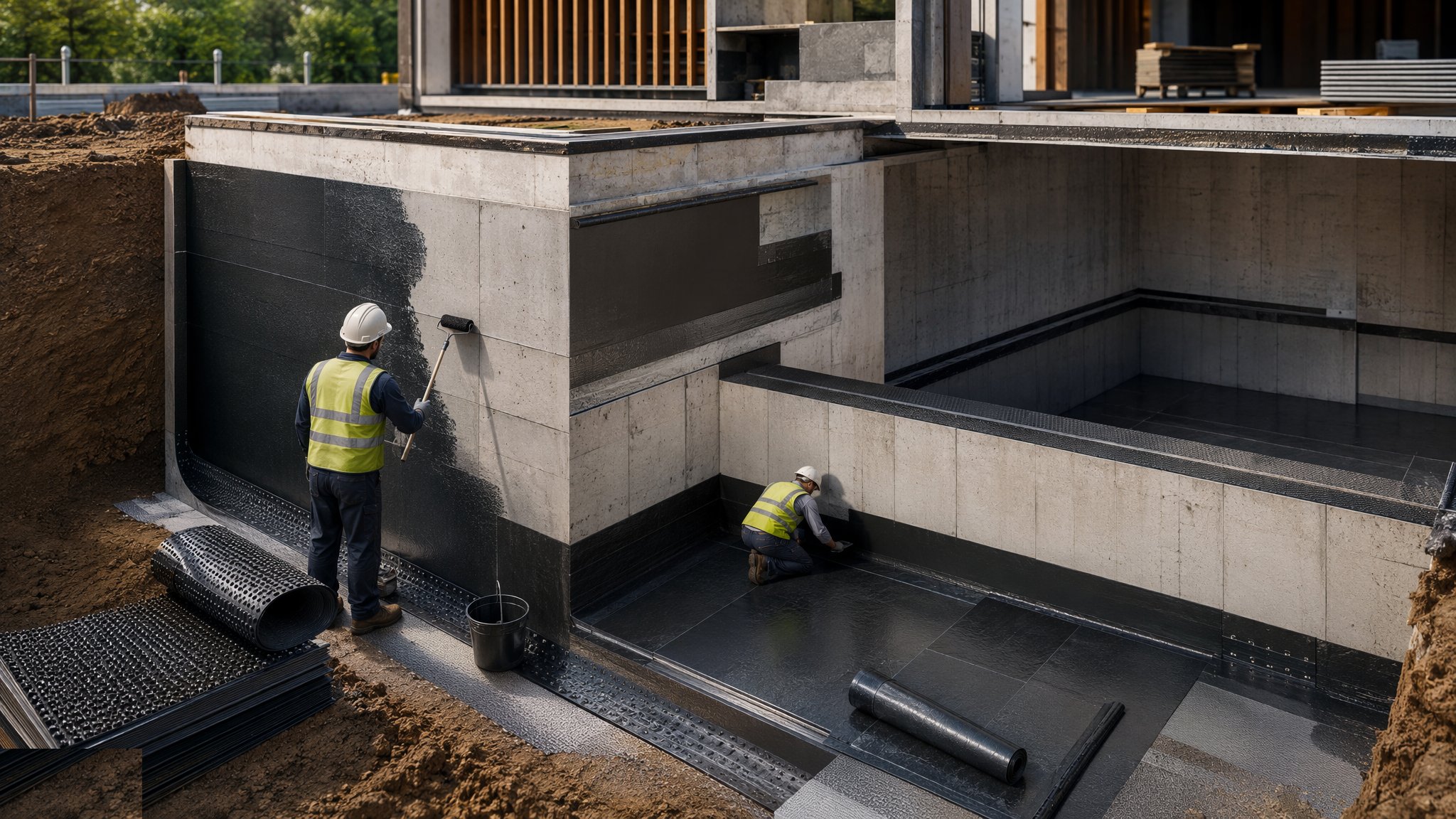
Below-ground waterproofing is the one package where a defect cannot be patched from outside afterwards — the earth goes back, the landscaping goes on, and the next time anyone sees the membrane is when water is coming through the wall inside. BS 8102 sets out the three recognised approaches: Type A, barrier protection — a membrane or coating applied to the structure that the water never gets past; Type B, structurally integral protection — the concrete box itself is the waterproofing, with waterbars and crack control doing the work; and Type C, drained cavity protection — the water is allowed through the structure, collected by a cavity drain membrane and pumped or drained away. Most serious basements combine at least two, because every system has a failure mode and belts and braces are cheap compared with digging up a finished garden.
The commercial reality on site is that Type A wins tenders and Type C wins arguments. A bonded sheet or liquid membrane is cheap to price and quick to apply, but it depends absolutely on substrate preparation, laps, and workmanship that is buried and uninspectable within weeks — and when it leaks, there is no maintenance route that does not involve excavation. A Type C cavity drain system accepts minor ingress and manages it behind a maintainable, accessible layer; it costs more up front but it is the only approach with a genuine whole-life answer. That is why warranty providers and basement specialists increasingly push drained systems, and why the specification argument at pre-construction is worth having properly.
Above ground the same logic applies in miniature: flat roof membranes live or die on falls, laps and upstands, and wet-area tanking in bathrooms and showers fails at corners, penetrations and the tray junction — almost never in the middle of the wall. In the UAE, below-ground work faces high saline water tables on coastal plots, and roof waterproofing takes a beating from UV and thermal cycling; liquid-applied and torch-applied membranes dominate, with DCD and municipality approval of systems and applicators.
When and why is Waterproofing and Tanking used?
Waterproofing follows the excavation and structure: below-ground systems go on as the basement box completes and before backfill, roof membranes follow the deck and insulation build-up, and wet-area tanking happens just before tiling at second fix. The choice between Type A, B and C is driven by ground conditions, water table, the use of the space (a plant room tolerates risk a bedroom does not), the warranty requirement, and honest assessment of who is maintaining it in year ten.
Types of Waterproofing and Tanking
Type A — barrier protection
Bonded sheet membranes, liquid-applied coatings or bentonite applied to the outside (or inside) of the structure to stop water at the face. Performance depends entirely on substrate preparation, laps and protection before backfill.
Type B — structurally integral
The concrete box itself is designed as the barrier: waterproof concrete with waterbars at joints, crack-width control, and sealed service entries. Common on UK basements and standard practice for UAE basement boxes.
Type C — drained cavity
Studded cavity drain membranes on walls and floors collect any ingress and channel it to a sump and pump or a gravity drain. Maintainable and accessible — the interior stays dry even if the structure leaks a little.
Roof waterproofing systems
Reinforced bitumen membranes (torch-applied), single-ply sheets (PVC, TPO, EPDM) and liquid-applied systems over the deck and insulation build-up. Falls, outlets, upstands and penetrations are the battleground.
Wet-area tanking
Cementitious or liquid-applied tanking under tiles in showers, bathrooms and plant rooms — full-height in shower zones, with preformed corner tapes, pipe collars and sealed tray junctions.
Waterproofing and Tanking: step by step
Step 1: Set the strategy and the grade

BS 8102 grades the internal environment — Grade 1 tolerates some seepage (car parks, plant rooms), Grade 2 wants no visible water but tolerates vapour, Grade 3 (habitable rooms) demands a dry space. The grade, the ground conditions and the water table drive whether you need one form of protection or two combined. Write the strategy down before the box is designed, because Type B has to be in the concrete design, not bolted on after.
Step 2: Prepare the substrate — properly
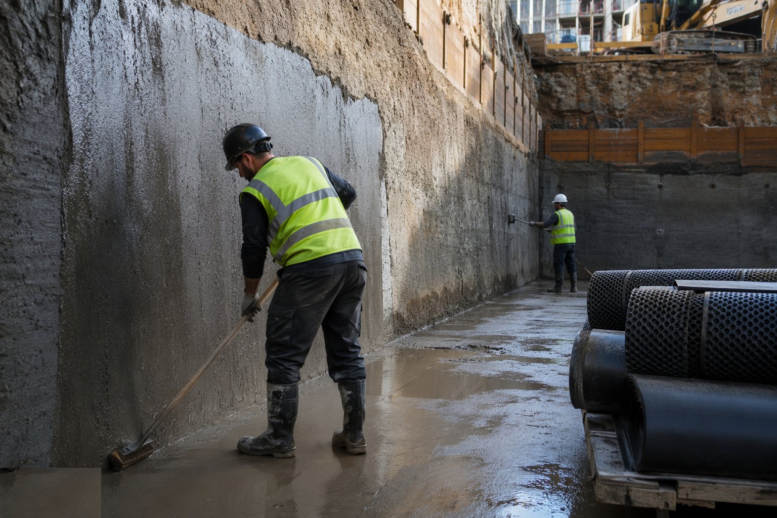
Every Type A failure story starts here. The surface must be clean, sound, smooth and dry to the membrane manufacturer's limits: fill tie holes and blowholes, grind off fins, round or fillet internal corners, chase out and repair honeycombing. Sheet membranes need priming; liquid systems need the moisture content checked with a meter, not a guess. If the substrate is wrong, stop — the membrane will faithfully copy every defect into a leak path.
Step 3: Install Type B joints and waterbars
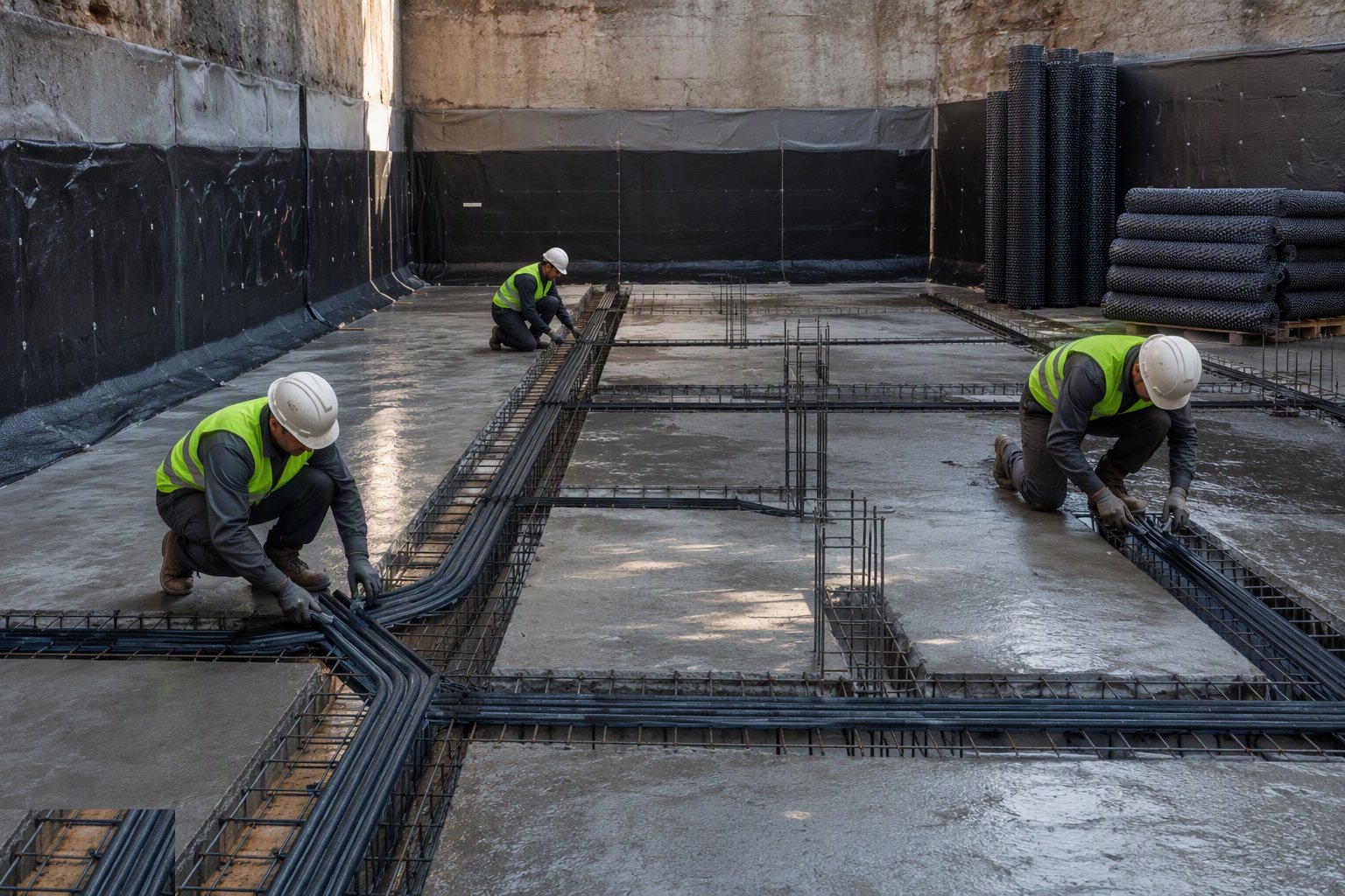
For a structurally integral box, the waterproofing is in the pour sequence: waterbars centred and fixed at every kicker, day joint and movement joint, kicker height to spec (typically 150 mm minimum), kickers cast with the slab or properly roughened and cleaned. Service penetrations get puddle flanges or hydrophilic seals set before the pour. Crack control comes from the reinforcement and the pour plan — there is no remedial easy fix for a leaking cold joint.
Step 4: Apply the Type A membrane
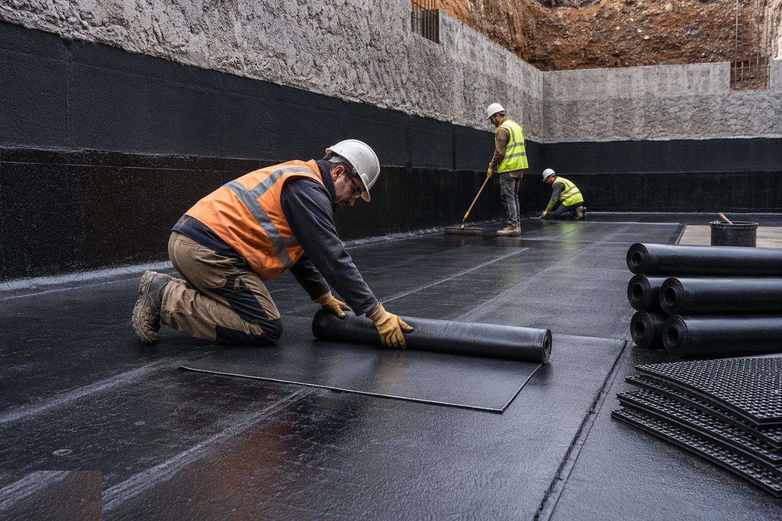
Sheets are laid to the lap schedule — typically 100 mm side laps, 150 mm end laps — rolled firm, with seams tested as you go; torch-applied membranes want an even bleed of bitumen at the lap, not a charred edge. Liquid systems go on in the specified coats to the specified wet-film thickness, checked with a gauge. Around penetrations, corners and terminations use the preformed details and tapes. Terminate at the DPC line or above the water table as the drawings show, never short.
Step 5: Protect it before backfill
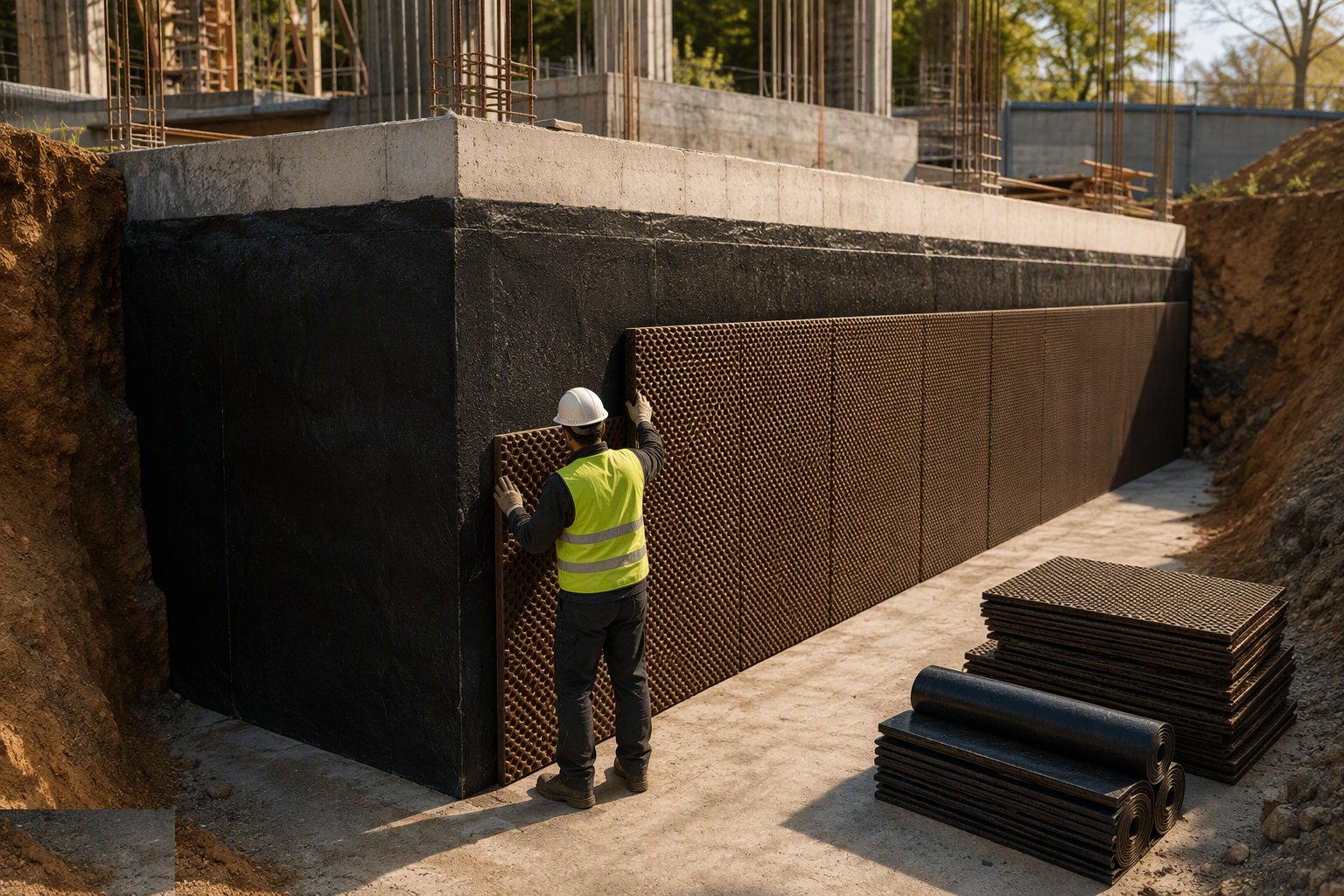
A finished membrane on a basement wall has hours of vulnerability: protection boards or a drainage/protection layer go on before a single bucket of backfill. Backfill in layers with selected material — no rubble, no frozen lumps, no compaction plant tight against the wall. Most "mystery" basement leaks are damage done in this step by a machine in a hurry.
Step 6: Install the Type C drained system
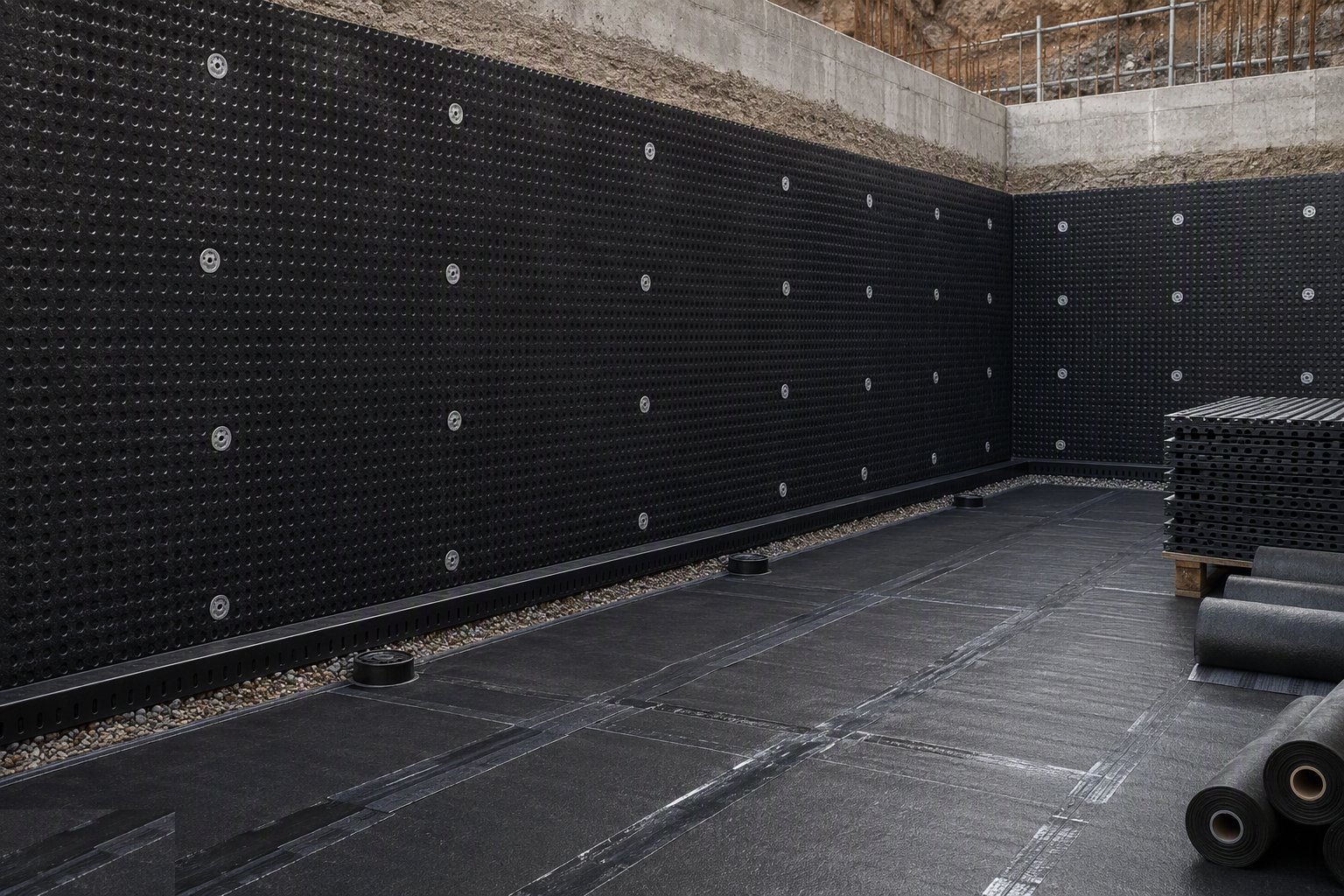
Wall membrane is fixed with sealed plugs at the specified centres, floor membrane laid with overlaps taped, and the perimeter drainage channel bedded at the wall-floor junction with rodding eyes. The sump chamber, pump, battery backup and high-level alarm go in and are commissioned before the floor finish. Document the system layout — the whole point of Type C is that someone can maintain it, and they can only maintain what they can find.
Step 7: Lay the roof waterproofing
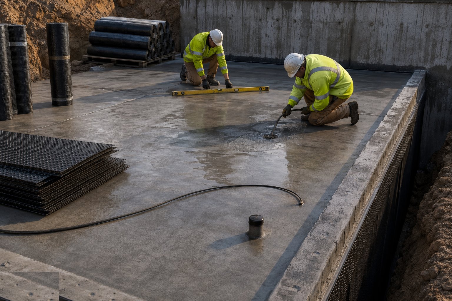
Check falls to outlets with a level and a hose before any membrane — ponding on a flat roof shortens the life of any system. Torch-on membranes go down in the specified layers with staggered, tested laps; single-ply is loose-laid or bonded with mechanically fixed seams welded and probe-tested. Upstands rise at least 150 mm above finished roof level, into chases or under counter-flashings, and every penetration gets a preformed boot or a proper pitch pocket.
Step 8: Tank the wet areas
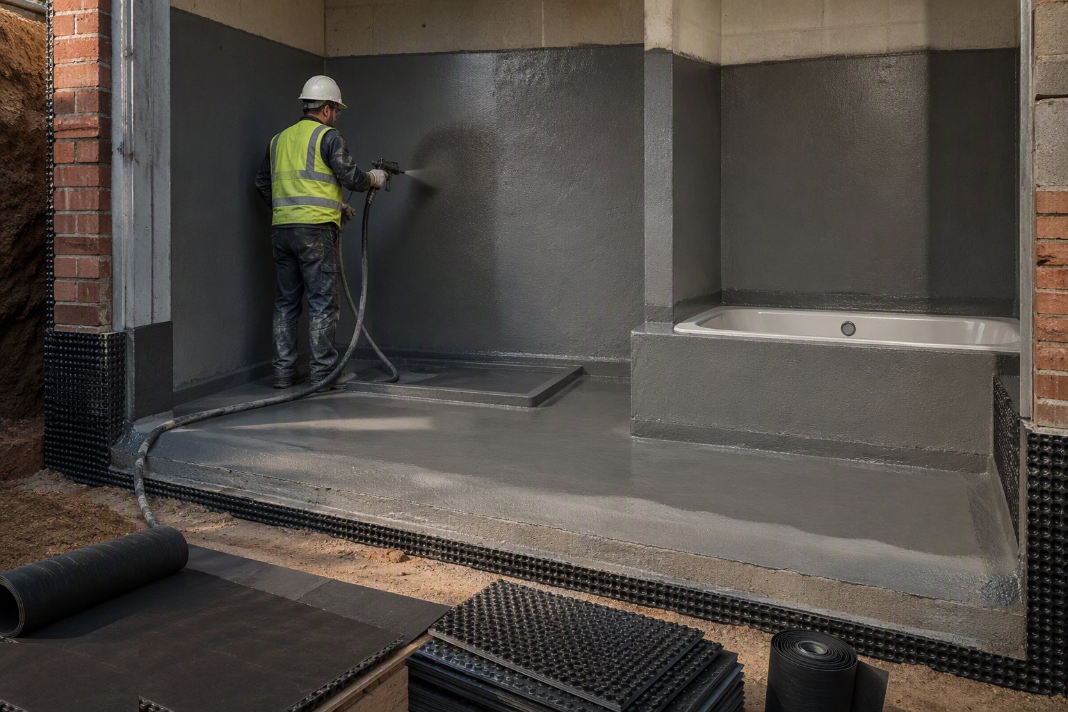
In showers and wet rooms, tank the floor and full height in the spray zone, carry the floor membrane up the wall 150 mm and the wall membrane over the bath rim and tray upstands. Preformed internal and external corner tapes, pipe collars and drain connectors are not optional extras — they are where these systems leak when the corners are brushed over. Flood-test the tray and floor for 24 hours before tiling, with the outlet plugged.
Step 9: Test, commission and record
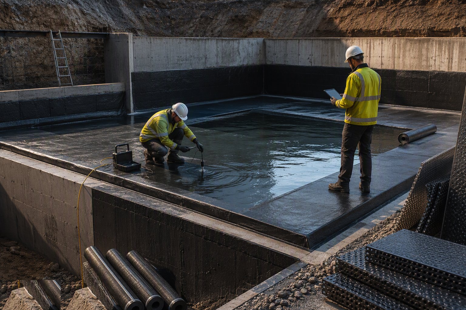
Roof: flood-test or electronically leak-test the membrane before coverings or finishes. Basement: commission the Type C pump and alarm, record discharge tests, and hand over the maintenance manual with the system layout. Every buried or covered layer gets photographed in progress with laps visible. Warranty providers (NHBC in the UK) and DCD/municipality inspectors in the UAE will want the records — assemble them as you go, not at handover.
Plant and equipment
- Torch-on gas sets, hoses and hot-air welders
- Seam probes, rollers and lap testers
- Wet-film thickness gauges and moisture meters
- Grinders, needle guns and substrate preparation kit
- Spray or squeegee rigs for liquid-applied systems
- Electronic leak-detection and flood-test equipment
- Sump pumps, discharge sets and commissioning kit (Type C)
- Kettles, tanks and PPE for hot bitumen work
Quality control checks
- Substrate condition signed off before membrane application — cleanliness, moisture, profile
- Lap widths, seam tests and wet-film thickness checked and recorded per shift
- Waterbar placement and kicker details photographed before every pour
- Flood tests or electronic leak tests on roofs and wet areas before covering
- Type C pump commissioning, alarm and backup tests recorded
- Manufacturer-approved applicators used where the warranty requires it
- Backfill material and protection layer inspected before burial
Safety considerations
- Hot works: torch-on membranes and hot bitumen — fire watch, extinguishers, permits to work
- Solvent-based primers and liquids under COSHH — ventilation in enclosed basements, RPE
- Basement work: confined-space assessment, gas monitoring, emergency egress
- Working at roof edges and around open outlets — edge protection and covers
- Manual handling of membrane rolls and protection boards
- UAE summer work: heat stress on roofs — early starts, shade, hydration, midday rules
Common defects
- Leaking laps from dirty substrate, short laps or untested seams
- Membrane punctured during backfill — no protection layer, rubble in the fill
- Cold-joint leaks in Type B boxes where waterbars were displaced or omitted
- Ponding roofs from failed falls, blocked outlets or settled decks
- Upstands too low, or terminations relying on mastic instead of a chase
- Wet-area leaks at corners and penetrations where tapes and collars were skipped
- Type C sumps never maintained — pump failure and a flooded basement five years on
- Type A specified alone on a Grade 3 space to save money, leaking with no repair route
Best suited for
- Type A + Type B combined — UK basements where the warranty wants two forms of protection
- Type C — habitable basements, retrofits and anywhere maintainability matters more than first cost
- Torch-applied and single-ply membranes — flat and low-slope roofs, podium decks and planters
- Cementitious and liquid tanking — showers, wet rooms, plant rooms and lift pits
- Type B boxes — UAE basements where the water table and salinity punish anything less robust
How long does Waterproofing and Tanking take?
Typical duration: Membrane on a basement wall elevation: 2–5 days including preparation and protection. Type C fit-out in a house basement: 1–2 weeks with drainage and commissioning. A house flat roof: 2–4 days. Wet-area tanking per room: 1 day plus cure and flood test..
Related processes
- Dewatering & Groundwater Control
- Shallow Foundations
- Piling & Deep Foundations
- Basement & Substructure
- Concrete Frame Construction
- Steel Frame Construction
- Masonry & Timber Frame
- Floor Slabs & Screeds
- Roofing
- Façade & Cladding
- Insulation Systems
- Windows, Doors & Glazing
- Site Access & Enabling Works
- Site Clearance & Demolition
- Setting Out & Survey Control
- Earthworks & Excavation
- MEP First Fix
- Internal Finishes
- MEP Second Fix & Commissioning
- External Works & Landscaping
- Testing, Handover & Snagging
- Waterproofing and Tanking in Commercial & Workplace
- Waterproofing and Tanking in Water Infrastructure
- Waterproofing and Tanking in Wastewater & Sewerage
- Residential & Housing sector guide