Survey, Ground Investigation & Resource Studies
Fixing where everything goes, proving what the ground will take, and measuring the wind, water and grid the asset is being built for.
Last updated 2026-07-28 by the BuildPedia Editorial Team.
What is Survey, Ground Investigation & Resource Studies?
Energy projects stake more on data than almost any other sector. A wind farm is financed on its measured wind resource; a hydro scheme on its hydrology; a solar farm on ground that will accept tens of thousands of driven posts; and all of them on a grid connection that exists on paper long before it exists in copper. Survey, ground investigation and resource studies all land at this stage because every downstream design decision — foundation type, pile depth, cable route, export capacity — is built from them.
Ground investigation in the UK follows BS 5930, the code of practice for ground investigations, with design derivation to BS EN 1997-2 (Eurocode 7 ground investigation and testing). The energy twist is the technology-specific field testing: solar pile design is verified by site-specific pull-out tests on trial posts driven across the array field, because the post embedment is short, the loads are uplift and lateral, and the ground changes every hundred metres. In the Gulf the ground signs its own name: dune sands and sabkha with saline groundwater, so the sulphate and chloride chemistry matters as much as the strength testing.
The resource and grid studies run on longer clocks than the GI. Wind resource is measured by met masts and increasingly by LiDAR, typically for a year or more before the energy yield is bankable; hydro schemes need continuous hydrometric records and flood analysis. Grid connection is the study that most often sets the programme: in the UK, distribution-scale schemes apply to the DNO and transmission-scale schemes to the transmission system operator — NESO (the National Energy System Operator, formerly National Grid ESO) — with connection queues and milestone compliance dominating timescales; in the UAE, connection runs through DEWA in Dubai and EWEC and TRANSCO in Abu Dhabi. The cable route to the point of connection is surveyed like a project in its own right.
When and why is Survey, Ground Investigation & Resource Studies used?
Survey, GI and resource studies follow access — the rigs, masts and survey crews have to be able to get in — and precede every foundation and electrical design decision, because the works themselves will destroy the ground surface and the data has to be captured first. It matters because design without this data is guessing with somebody else's money: a pile design assumed rather than pull-out tested fails in service, and a grid application made late means the connection date, not the construction, decides when the asset earns revenue. At domestic scale the same data-first logic survives intact: a rooftop PV job starts with a structural check of the roof and a yield estimate from measured irradiation data, and a ground-source heat pump starts with a room-by-room heat-loss calculation — smaller datasets, same rule that design without data is guessing.
Types of Survey, Ground Investigation & Resource Studies
Topographic and utility surveys
GNSS and total-station topographic surveys, increasingly supplemented by drone photogrammetry over large array fields, plus utility tracing with cable avoidance tools and ground radar. They fix the site model everything is designed on and expose the buried constraints — existing cables, pipelines and drainage — before the design locks in.
Ground investigation and in-situ testing
Boreholes, trial pits and CPTs to BS 5930 practice, sized to the technology: shallow and dense across a solar field, deep at turbine and powerhouse positions. For solar, trial posts and pull-out tests verify the driven-pile design against real ground; laboratory testing adds the strength, consolidation and — in saline ground — the chemistry.
Resource measurement studies
The technology's own data campaign: met masts with anemometry at hub height and ground-based LiDAR for wind, typically run for a year or more; river gauging, level logging and hydrological analysis for hydro. These datasets underpin the energy yield assessment the project is financed on, so their quality controls are unforgiving.
Grid connection and cable-route studies
The electrical feasibility work: capacity applications, load-flow and fault-level studies at the agreed connection point, and the survey of the cable route to it — utility records, ground radar and trial holes along the whole run. In the UK the route crosses DNO and NESO processes; in the UAE, DEWA, EWEC or TRANSCO approvals shape the connection design.
Survey, Ground Investigation & Resource Studies: step by step
Step 1: Desk study and constraints mapping
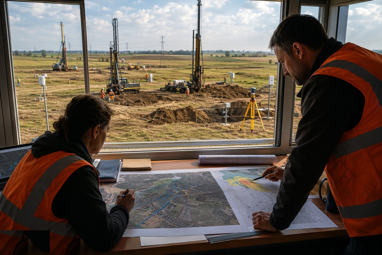
Start in the office: geological mapping and historical land use, previous GIs, utility records, flood data, and the existing network studies for the grid connection. For a wind or hydro scheme add the long-run climate and flow records. Walk the site with the desk study in hand, confirming features and noting where the rigs and masts can physically go. The desk study defines what the fieldwork must answer.
Step 2: Establish control and survey the site
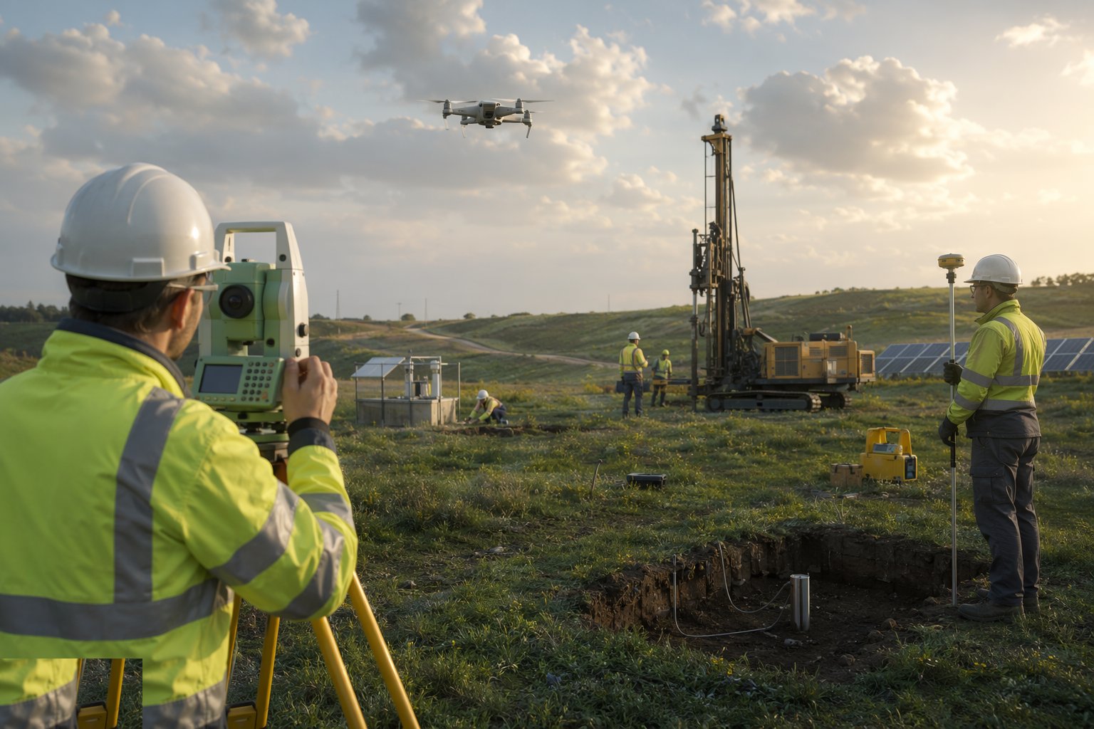
Establish the primary survey control network tied to the national datum — Ordnance Datum Newlyn in the UK, the municipality datum in the UAE — then run the topographic survey and utility trace. Set out and record every proposed borehole, trial pit, mast and gauge position from the control. On a solar field of tens of hectares, drone photogrammetry earns its keep here — but the control network is still the skeleton everything hangs on.
Step 3: Design and clear the ground investigation
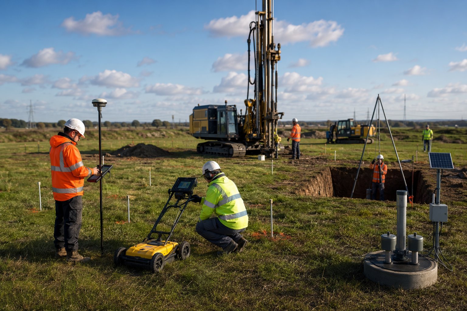
Fix the exploratory hole locations, depths and methods against the proposed works: boreholes at turbine, substation and powerhouse positions, a grid of shallow holes and CPTs across the array field, trial pits where shallow variability matters. Every position gets the same service-clearance discipline as construction excavation — CAT scan, marked positions, hand-dug proving where records conflict. The GI designer signs off the scope before mobilisation.
Step 4: Carry out the intrusive works and laboratory testing
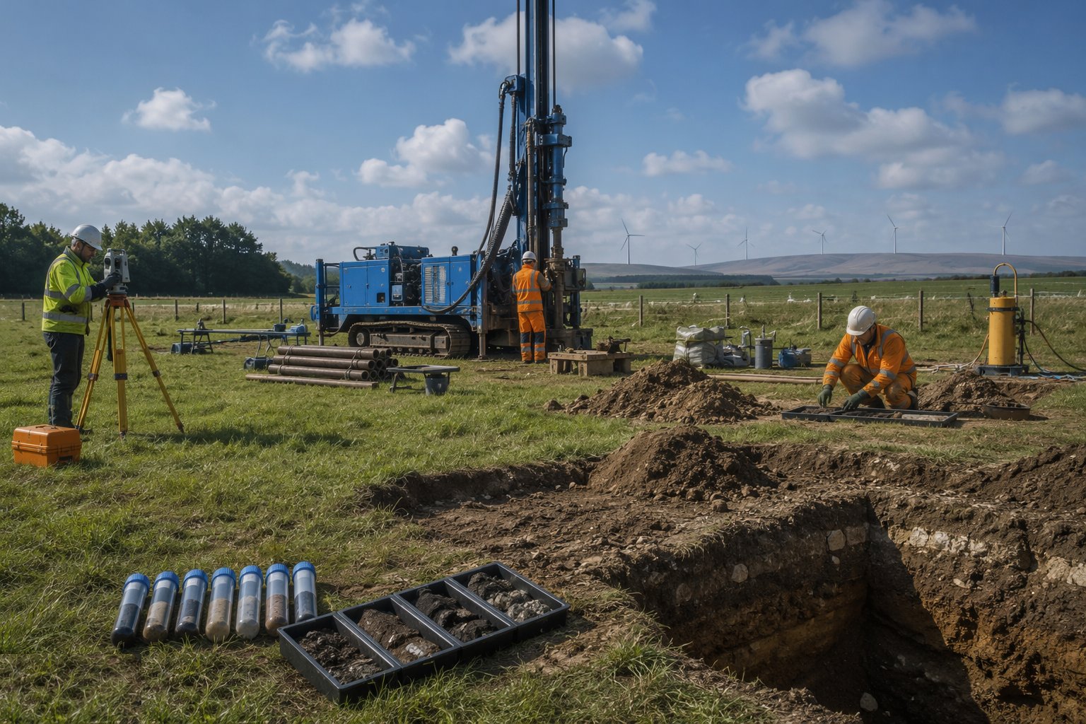
Drill the boreholes, push the CPTs, dig the pits — logging every stratum, groundwater strike and obstruction. Take disturbed samples for classification and undisturbed samples for strength and consolidation testing, and install piezometers where groundwater matters. Laboratory testing covers classification, strength and compaction, and in saline Gulf ground the chemistry — sulphate and chloride contents of soil and groundwater that set the durability class of everything buried.
Step 5: Run the technology-specific field tests
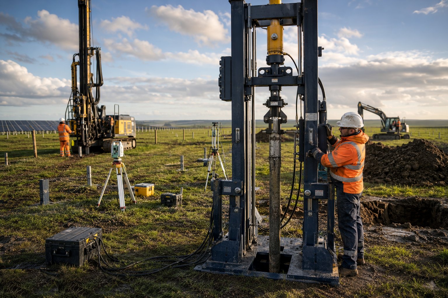
For solar, drive trial posts across the field — every ground type, every slope aspect — and pull-test them to a written procedure with calibrated load and displacement measurement: the results set the embedment depth and post section for the production piles. For wind, verify foundation-bearing conditions at each turbine position. For hydro, confirm the diversion and foundation ground at the dam and powerhouse. These tests translate the GI into design numbers.
Step 6: Install and monitor the resource campaign
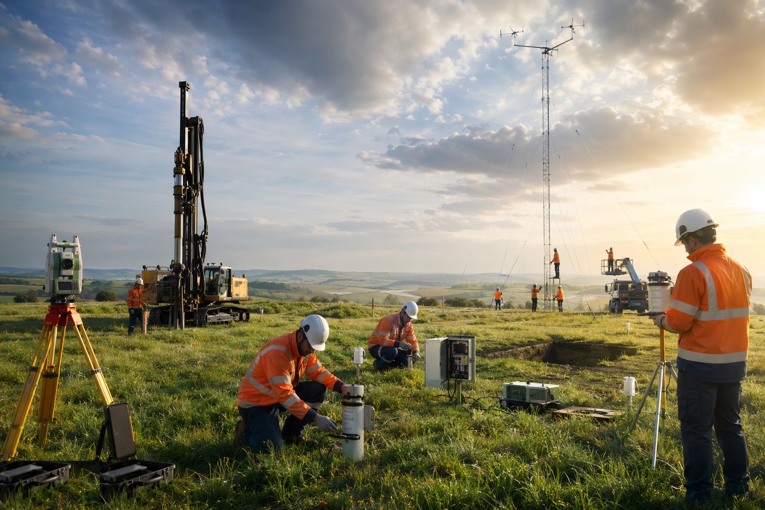
Erect the met masts with calibrated anemometry at the heights the yield assessment needs, or deploy the LiDAR units — working-at-height and remote-site rules apply — and start the data loggers. For hydro, install the gauging: level loggers, current metering and, where justified, a rated weir. Protect the instruments from stock, vandalism and lightning, and service them on a schedule — a three-month data gap in a twelve-month campaign can make the whole dataset unusable for financing.
Step 7: Grid connection application and system studies
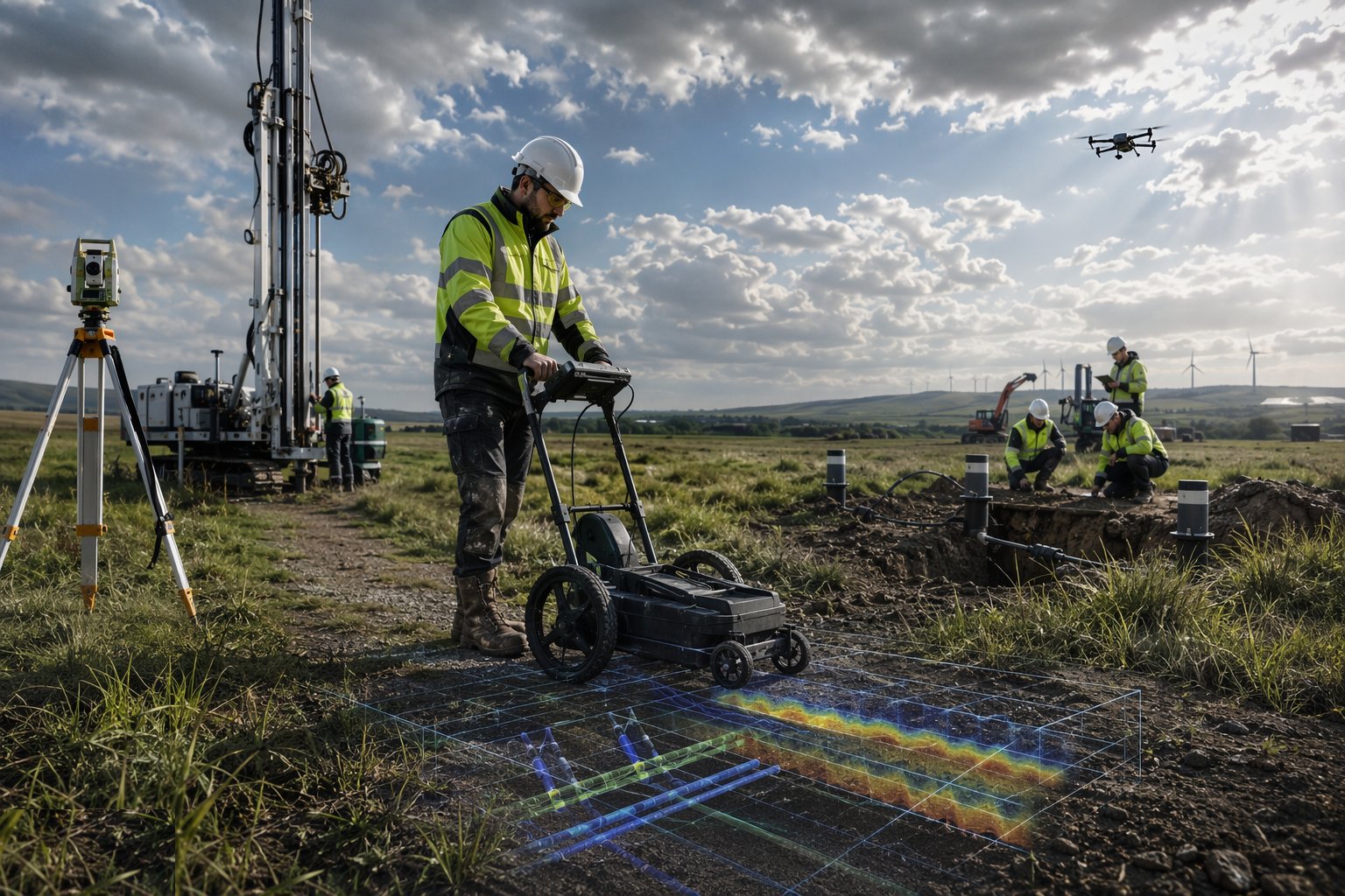
Lodge the connection application early — in the UK, with the DNO for distribution-scale export or through the transmission process for larger schemes, where connection queues and milestone compliance under the reformed connections process dominate timescales; in the UAE, through DEWA, EWEC or TRANSCO as the emirate dictates. Run the load-flow, fault-level and protection studies at the agreed point of connection, and survey the cable route end to end — records, radar and trial holes — so the route in the application is the route you can actually build.
Step 8: Report: factual then interpretative
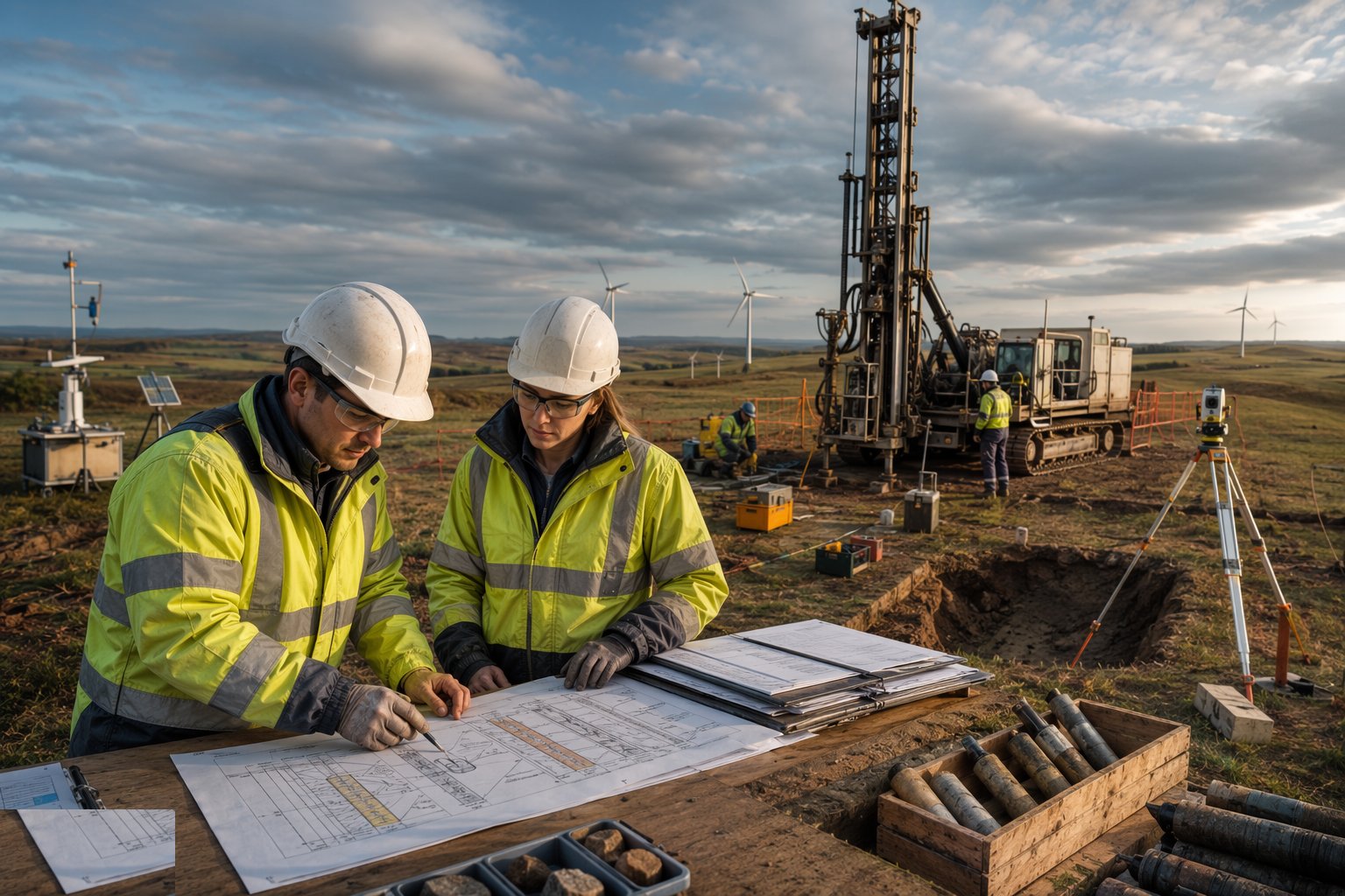
The factual ground investigation report presents the logs, tests and monitoring without opinion; the interpretative report derives the design parameters, flags the residual risks and recommends what the designer must do about them. The resource data goes to the yield analysts, the grid studies to the electrical designer. Design proceeds from these reports — not from hopeful assumptions carried over from the feasibility stage.
Plant and equipment
- Total stations, GNSS RTK rovers and survey drones
- Cable avoidance tools and ground-penetrating radar for utility tracing
- Borehole rigs, CPT rigs and trial-pit excavators
- Driven-post test rig and calibrated pull-out test frame for solar trials
- Met masts, anemometry and ground-based LiDAR units
- Hydrometric equipment: level loggers, current meters and gauging weirs
- Standpipes, piezometers and dipmeters for groundwater monitoring
Quality control checks
- GI scope signed off by the geotechnical designer before mobilisation
- Borehole and trial pit logs completed in the field and checked against samples taken
- Pull-out tests to a written procedure, with calibrated load and displacement measurement
- Meteorological and hydrometric data quality-checked continuously; instrument calibration certificates held
- Grid studies based on the agreed connection point and export capacity, not assumed values
- Sulphate and chloride chemistry on soil and groundwater in saline ground
- Factual report audited against the hole and test schedule — no missing holes, no missing tests
Safety considerations
- Service clearance and permit to dig at every intrusive position — the GI is not exempt
- Working at height and rescue planning for met-mast erection and instrument servicing
- Remote-site journey management and communications for survey crews
- Working near water during hydrometry — buoyancy aids, bank-side controls and lone-working rules
- Rig stability on soft ground and slopes — outrigger mats and bearing checks
- Heat management and midday-break compliance for field crews in the Emirates
Common defects
- Wind campaign too short or riddled with data gaps — the yield assessment is downgraded and the financing wobbles
- Pull-out tests skipped; post design based on desktop assumptions — posts refuse in driving or pull out in service
- Groundwater level taken on drilling day only, missing the seasonal high
- Grid application lodged late — the connection date, not construction, ends up setting the programme
- Chemistry testing omitted in saline ground — durability class guessed, not derived
- Cable route surveyed from records alone; an obstruction appears at excavation
- Trial pits and test posts left unfenced or badly backfilled across the future array field
Best suited for
- Fixing where the asset and its infrastructure will actually go
- Ground investigation proving foundations for machines and plant
- Measuring the wind, water or irradiance resource the design banks on
- Grid, environmental and consenting studies that shape the scheme
How long does Survey, Ground Investigation & Resource Studies take?
Typical duration: GI and surveys typically 6–12 weeks of fieldwork plus 4–6 weeks of testing and reporting; wind resource campaigns run for 12 months or more and start well ahead of construction; grid studies run in parallel and often control the programme..
Related processes
- Site Access & Enabling Works
- Piling & Mounting Structures
- PV Module Installation
- Electrical Balance of System
- Grid Connection & Energisation
- Wind Turbine Foundations
- Craneage & Tower Erection
- Wind Farm Electrical Infrastructure
- Commissioning & Energisation
- River Diversion & Cofferdams
- Dam & Powerhouse Civils
- Electromechanical Installation
- Impoundment, Commissioning & Handover
- Ground-Source Heat Pumps — Homes & Villas
- Shallow Geothermal — Commercial & District Schemes
- Deep Geothermal Drilling & Wells
- Geothermal Plant, Connection & Commissioning
- Survey, Ground Investigation & Resource Studies in Oil & Gas / Petrochemical
- Power Generation sector guide
- Utilities & Energy group