Piling & Mounting Structures
Thousands of driven steel posts and the racking they carry — the repetitive, high-rate foundation system whose pull-out tests and driving logs decide whether the array stands for thirty years.
Last updated 2026-07-28 by the BuildPedia Editorial Team.
What is Piling & Mounting Structures?
A utility-scale solar farm has more foundations than almost any other structure ever built — tens of thousands of them on a large site, each one a galvanised steel post driven a metre or three into the ground. There is no excavation, no concrete in the typical case: driven posts (C, U, sigma or hat sections, hot-dip galvanised to BS EN ISO 1461 or the project spec) are installed by purpose-built pile drivers, increasingly GPS-guided from the design model, at rates of hundreds per machine per day. The whole foundation design rests on the site-specific pull-out testing done at investigation stage, because the loads are uplift and lateral from wind rather than compression from weight, and the ground changes character across every field. Production driving verifies the design continuously: refusal in cemented or stony ground triggers pre-drilling; a post that drives too easily triggers an engineering look at that zone.
The mounting structure bolts onto the posts, and its type decides the piling pattern. Fixed-tilt racking — posts, rails and purlins at a set elevation angle — is simple, robust and the default where land is cheap relative to steel. Single-axis trackers rotate the rows east to west following the sun and typically lift energy yield meaningfully — commonly quoted in the region of 15 to 25 per cent over fixed-tilt depending on latitude and climate, at the cost of heavier foundations (each tracker row is one driven pile per torque-tube bay, carrying higher overturning loads), motors, controllers and a wind-stow strategy that must work in a storm with the power out. In the Gulf, trackers dominate the large desert plants — Noor Abu Dhabi at Sweihan and Al Dhafra both use tracking and bifacial modules — while UK farms split between the two, with planning height limits and wind loading often favouring fixed-tilt.
The tolerances look loose by building standards and are anything but. Posts must be on line, on level and plumb within the racking manufacturer's adjustment range — typically tens of millimetres in position and a few degrees in plumb — because the rails and torque tubes have finite adjustment and a post driven outside it gets cut off, spliced or pulled and redriven, all of which are slow and all of which multiply across thousands of piles. In the Emirates the ground adds its own traps: cemented caliche layers that refuse posts or break the galvanising, sabkha patches with aggressive ground chemistry that demands heavier galvanising or coated sections, and desert wind-blown sand that buries survey control. The stage ends with the racking complete, torqued and surveyed, ready to receive modules.
When and why is Piling & Mounting Structures used?
Piling and mounting follows the survey and ground investigation directly — the pull-out test results from that stage are the pile design, and the setting-out control is what the drivers navigate from. It matters because it is the rate-setter for the whole mechanical build: modules cannot be hung until the tables exist, and the table count gates everything downstream. It matters structurally because the array's wind resistance is entirely in these posts — there is no redundancy — so the driving records, the refusal management and the galvanising integrity are the asset's thirty-year insurance policy. And it matters commercially because piling errors multiply: a systematic setting-out error or a mis-specified post section is repeated tens of thousands of times before anyone notices. The rooftop end of the sector replaces this process entirely: there are no posts to drive, just brackets fixed into rafters or ballast laid on a flat roof, with the building's structure doing the foundation's job — but the wind-uplift and pull-out arithmetic is the same arithmetic, checked against the roof rather than the soil.
Types of Piling & Mounting Structures
Driven-post fixed-tilt structures
Galvanised steel posts driven in rows, carrying rails and purlins at a fixed elevation angle set for the site latitude. The simplest and most maintainable option: no moving parts, light foundations, and fast erection with bolted connections. The UK default where planning height limits and wind exposure suit it.
Single-axis tracker rows
Long torque-tube rows rotating about a north-south axis on one heavier driven pile per bay, driven by motors and controllers with anemometer-triggered wind stow. Higher yield per module, especially in high-irradiation desert climates — the standard on the large Gulf plants — but with powered plant to install, commission and maintain, and larger foundation loads per pile.
Ground screws and ballasted structures
Alternatives where driving is impossible or undesirable: helical ground screws in refusal or rocky ground, and concrete ballast trays or blocks where penetration is prohibited — capped landfill, contaminated ground or high water tables. Both are slower and heavier on logistics, and ballasted systems trade the pull-out problem for a settlement and sliding one.
Piling & Mounting Structures: step by step
Step 1: Set out the pile grid and driving lanes
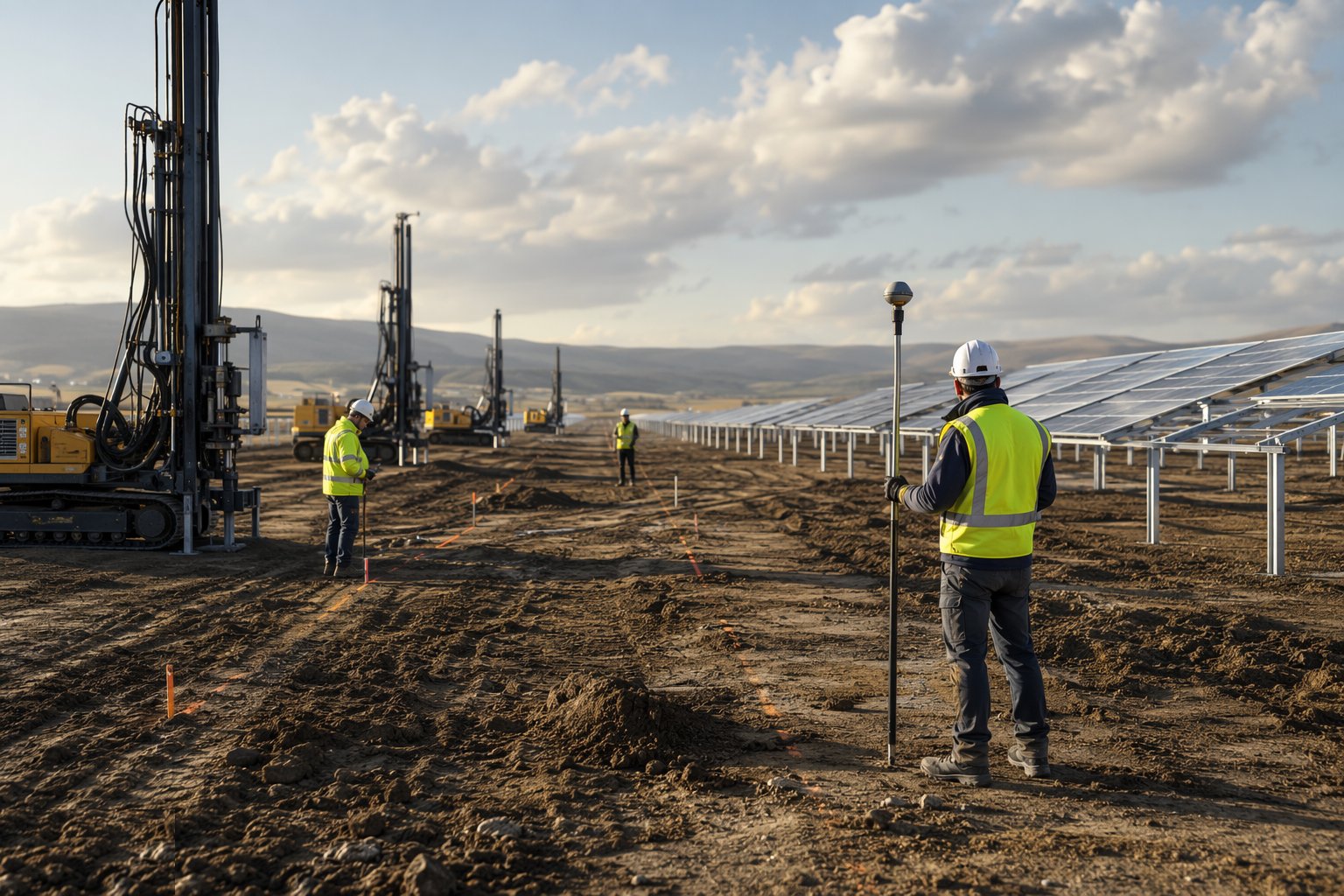
Translate the array layout into the drivers' working model: pile positions, row lines, driving lanes and the exclusion zones around boundary fences, drainage features and buried cables. Load the GPS-guided rigs with the design model and verify the transformation against the site control network with check shots on known points. Where rigs are not guided, set out with total station or GNSS rovers and mark each position — but understand that at thousands of posts, guidance errors scale, so the first rows of each block get a full dimensional check before production rolls.
Step 2: Prove the design with trial driving and pull-out verification
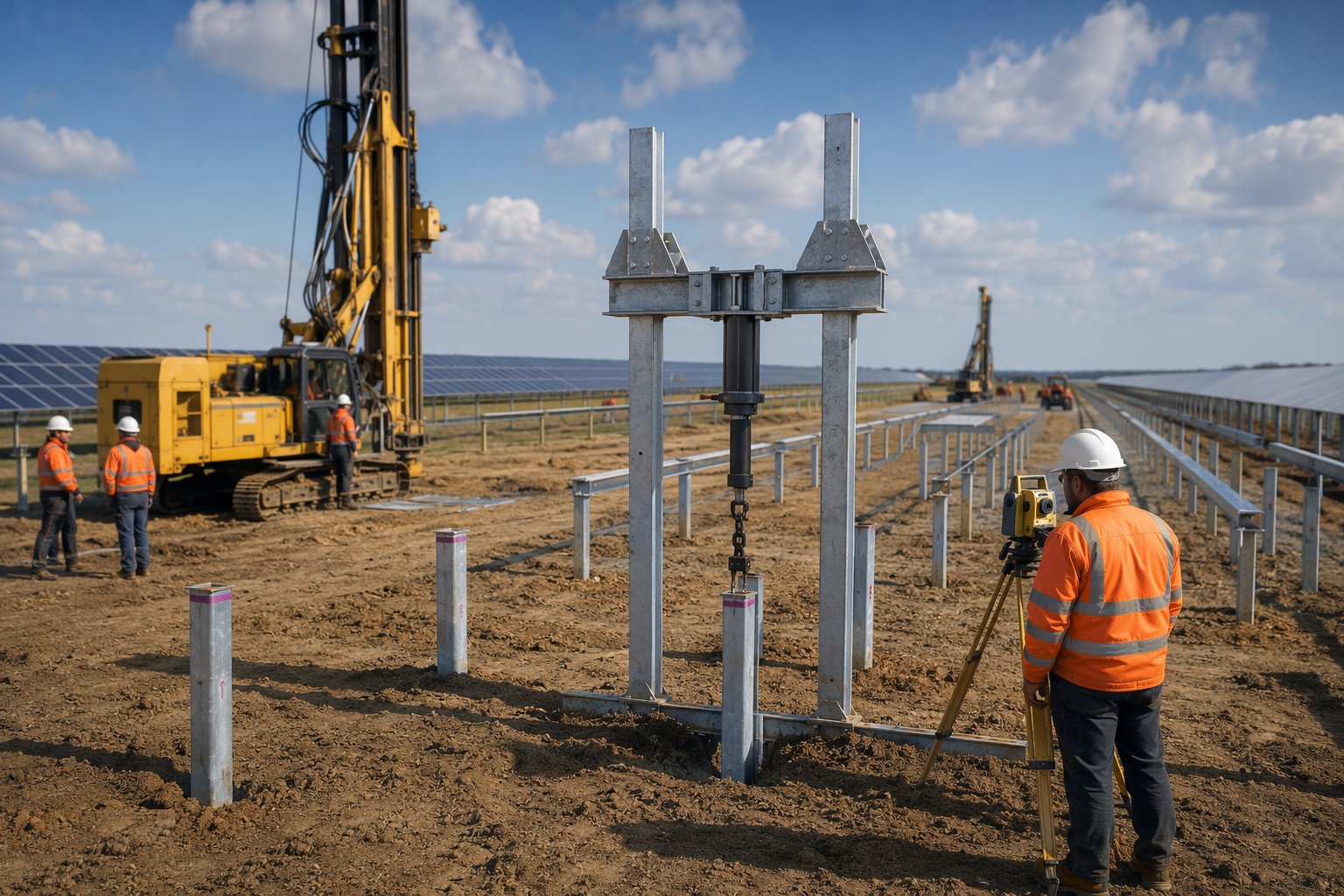
Before production, drive the trial posts across the field — every ground type, every slope — and verify against the investigation-stage pull-out results: embedment, refusal criteria and any pre-drill zones confirmed or adjusted. Where ground varies more than the GI suggested, extend the testing rather than assume; the cost of extra trial posts is nothing against a systematic under-design. Agree the production driving criteria — target embedment, refusal definition, remedial method — in writing with the designer.
Step 3: Drive production posts with logged QA
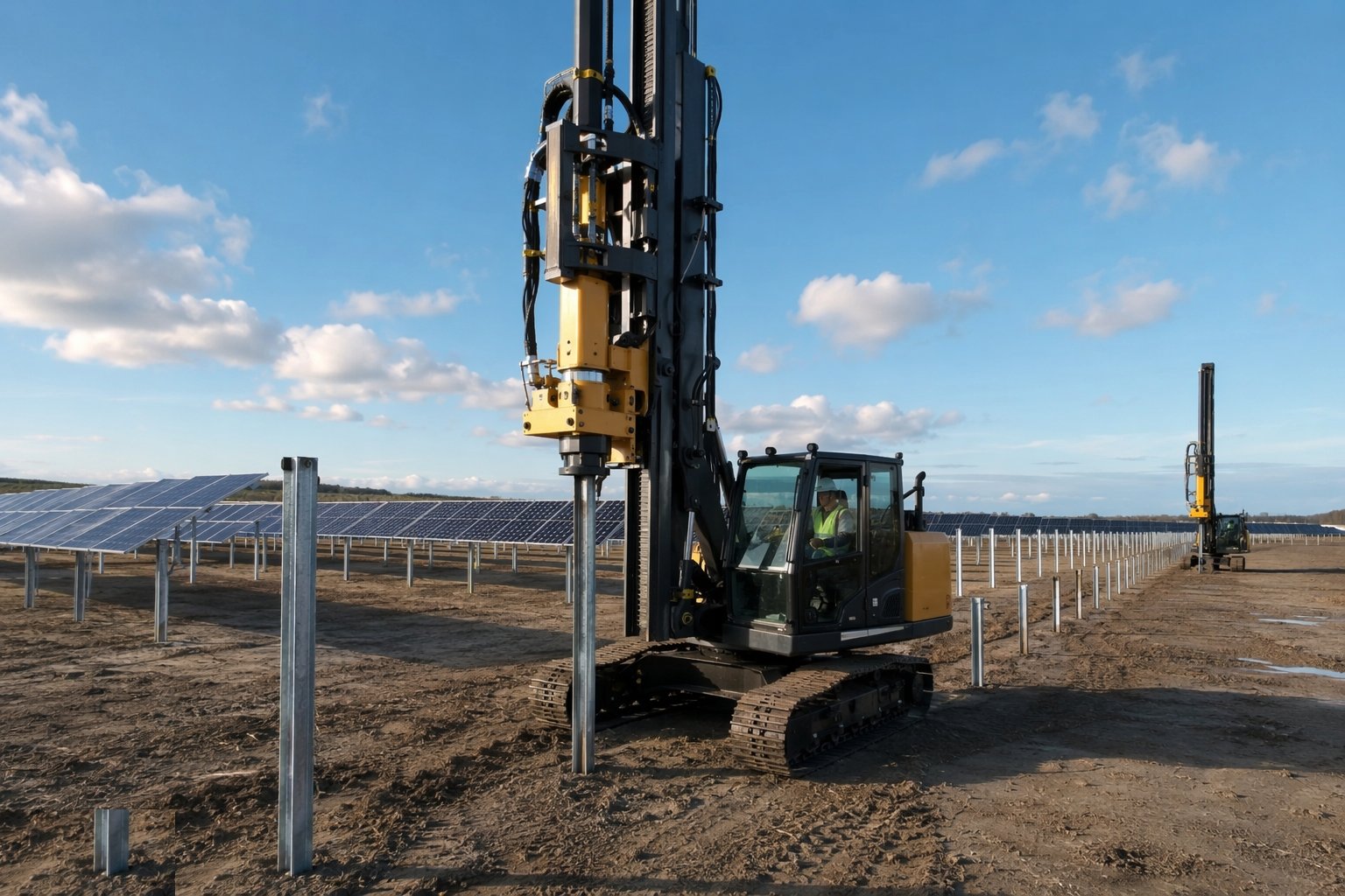
Drive with modern rigs that log every post — position, embedment, driving resistance or hammer energy, inclination — and upload the records against the pile schedule daily. Manage refusals to the agreed method: pre-drill through cemented layers rather than batter posts into refusal (broken galvanising and bent sections result), and engineer any zone where posts drive short or too easily. Keep the galvanising intact: posts that need cutting get treated cut ends, and dragged or dropped posts with coating damage are rejected or repaired per the spec.
Step 4: Survey and correct the installed posts
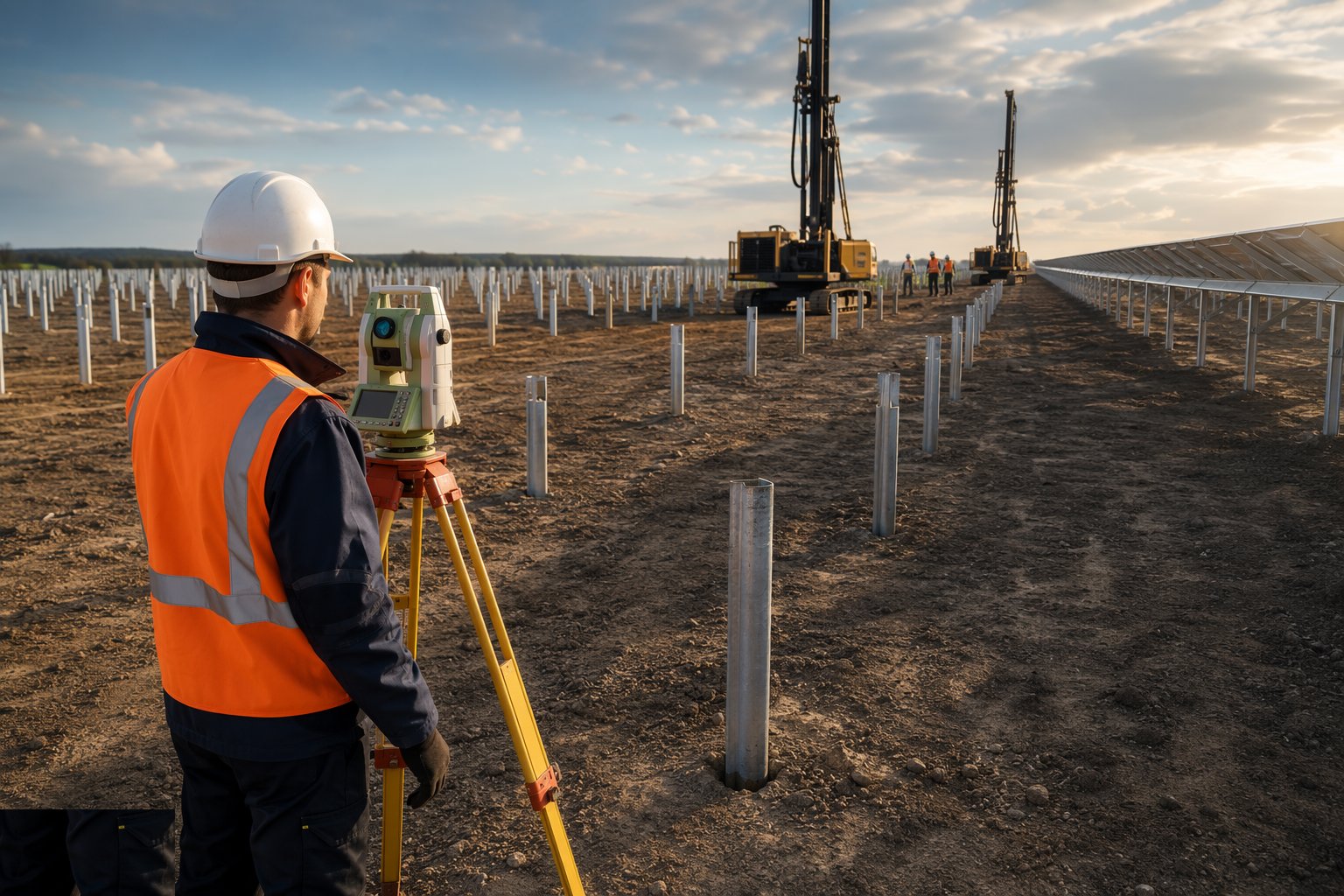
Run the as-driven survey against the tolerance envelope — position, top-of-pile level and plumb within the racking adjustment range — and programme corrections: cut and splice, extract and redrive, or engineer a local solution. This survey is the gate to racking erection; crews erecting onto unsurveyed posts will stall within a day on out-of-tolerance piles, and their stoppages cost more than the survey ever will.
Step 5: Erect the racking and torque-tube assemblies
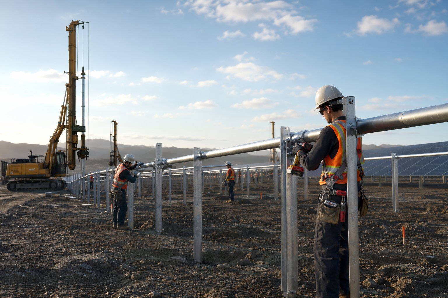
Bolt up the racking on the corrected posts: rails, purlins and bracing for fixed-tilt; bearing housings, torque tubes and drive posts for trackers. Set row alignment and rail level within the module clamping tolerances, and torque every structural bolt to spec with a marked-bolt or torque-record regime — untorqued connections are the classic latent defect, invisible until a wind event. Keep module delivery coordinated: racking completion gates module hanging, so the erecting sequence follows the module crews.
Step 6: Install tracker drives and wind-stow systems
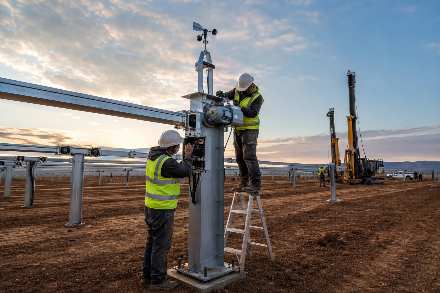
On tracker sites, install the motors, slew drives, controllers and anemometers, terminate the power and comms cabling, and commission row rotation and — critically — the wind-stow function, with the fail-safe mode proven before modules are hung on the row. Verify stow angles and response, because a tracker row full of modules caught flat in a gale is a sail. Record firmware versions and row addressing; the SCADA integration later depends on this addressing being right.
Step 7: Final alignment survey and release to module installation
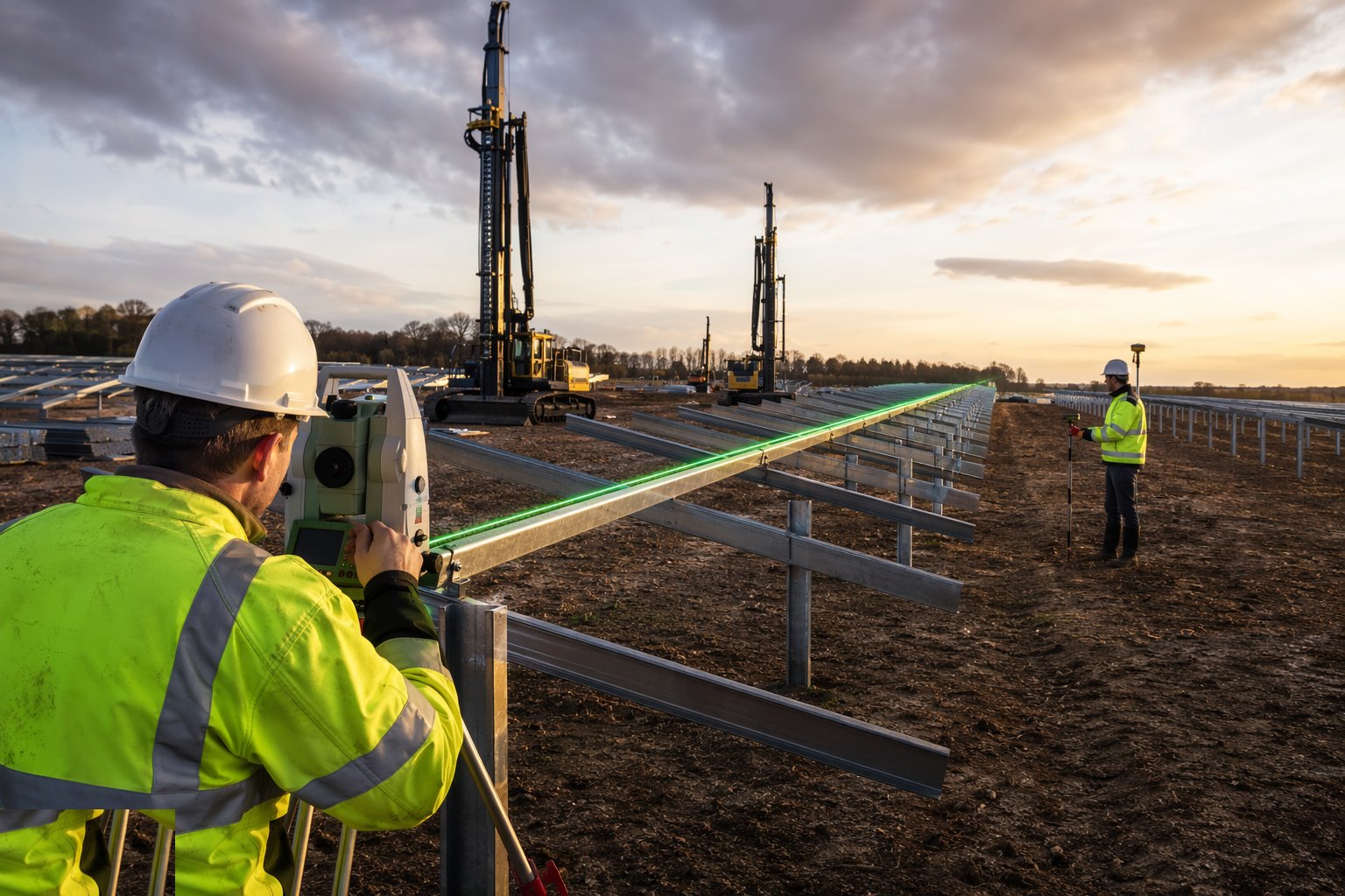
Complete the block-by-block release: alignment survey of rails or torque tubes, torque records closed, punch items from the racking erection cleared, and the table register — which tables are complete and module-ready — published daily to the module crews and the logistics team. The register is the coordination tool for the next stage: module deliveries, gangs and clamping equipment all schedule off it.
Plant and equipment
- GPS-guided pile-driving rigs with auto-logging
- Pre-drill auger attachments or separate drill rigs for refusal ground
- Galvanised steel posts, rails, purlins and torque tubes
- Torque wrenches and marked-bolt systems for structural connections
- GNSS rovers and total stations for setting out and as-driven survey
- Telehandlers and side-boom handlers for steel distribution
- Tracker motors, controllers, anemometers and comms cabling
- Pull-out test frames and load cells for verification testing
Quality control checks
- Pull-out verification completed and driving criteria agreed before production
- Every post logged: position, embedment, resistance, inclination — uploaded daily
- As-driven survey gates racking; corrections tracked to closure
- Galvanising integrity maintained; cut ends treated, damaged posts rejected
- Structural bolt torques recorded or marked-bolt regime audited
- Tracker wind-stow proven fail-safe before modules are hung
- Block release register maintained; table status published daily
- Ground chemistry records match post coating spec in sabkha zones
Safety considerations
- Piling rig stability on slopes and soft ground — mats and gradient limits
- Exclusion zones around driving rigs; struck-by and dropped-post controls
- Manual handling of rails and posts; mechanical aids the default
- Working around moving tracker rows during commissioning
- Dust, heat and midday-break compliance for desert driving campaigns
- Buried services and overhead lines cleared before any driving lane opens
- Noise and vibration management near boundaries and livestock
Common defects
- Posts driven to refusal without pre-drilling — bent sections and broken galvanising
- Systematic setting-out error — hundreds of posts off line before the first check
- Pull-out tests skipped for a ground type — under-embedded zone fails in a storm
- Posts cut down without coating repair — corrosion starts at the cut
- Bolts left untorqued across whole blocks — connections loosen in service
- Tracker stow not proven — row caught flat by the first gale
- Sabkha patch piled with standard galvanising — accelerated corrosion
- Racking erected on unsurveyed posts — module clamps out of adjustment range
Best suited for
- Thousands of driven posts installed at production rates
- Pull-out testing proving the foundation of the whole array
- Racking aligned across rolling or irregular terrain
- The repetitive system every module and cable lands on
How long does Piling & Mounting Structures take?
Typical duration: Typically 3–7 months for piling and structures on a 50–100 MW site with multiple rigs; the Gulf gigawatt plants run many crews in parallel for a year or more, with table completion phased to feed module installation continuously..
Related processes
- Site Access & Enabling Works
- Survey, Ground Investigation & Resource Studies
- PV Module Installation
- Electrical Balance of System
- Grid Connection & Energisation
- Wind Turbine Foundations
- Craneage & Tower Erection
- Wind Farm Electrical Infrastructure
- Commissioning & Energisation
- River Diversion & Cofferdams
- Dam & Powerhouse Civils
- Electromechanical Installation
- Impoundment, Commissioning & Handover
- Ground-Source Heat Pumps — Homes & Villas
- Shallow Geothermal — Commercial & District Schemes
- Deep Geothermal Drilling & Wells
- Geothermal Plant, Connection & Commissioning
- Power Generation sector guide
- Utilities & Energy group