PV Module Installation
Hanging the modules, clamping them to torque and wiring the strings — high-rate repetitive work where handling damage, clamp position and connector quality decide the plant's long-term output.
Last updated 2026-07-28 by the BuildPedia Editorial Team.
What is PV Module Installation?
Module installation is the most visible stage of a solar build and the most repetitive: on a large site, gangs hang thousands of modules a week, table by table, in a production rhythm fed by the table register from the structures stage. The work looks simple and damages easily. A PV module is a laminate of glass, cells and polymer that can suffer microcracks in the cells from handling abuse — a module carried on a shoulder, leaned against a post, stepped on or dropped onto a corner — that no visual inspection will catch and that will degrade output over years. The discipline is in the handling rules: two-person lifts or mechanical handlers, modules kept vertical, never walked on, never flexed, and pallets staged so nobody improvises. Sampling regimes on larger jobs — a proportion of modules flash-tested or electroluminescence-tested on receipt or after installation — exist precisely because handling damage is otherwise invisible.
Clamping is engineering, not tidiness. Modules clamp at the positions the manufacturer specifies on the frame — clamp zones are load-rated, and clamping outside them voids the mechanical load rating and usually the warranty — with bolts torqued to the specified value: under-torqued clamps let modules slip or lift in wind, over-torqued clamps distort frames and stress glass. String wiring follows: home-run cables loom along the rails in UV-stable ties and clips, off the ground and clear of sharp edges, with connectors crimped to the manufacturer's tooling and polarity checked string by string. Every frame bonds to earth through the racking, and every string gets its open-circuit voltage and polarity verified before it is paralleled into an inverter.
Climate writes its own rules into the stage. In the Gulf, modules go up in extreme heat: cell temperatures at installation can sit far above standard test conditions, thermal expansion gaps at clamps and between tables must be respected, and the working day bends around the midday summer restrictions. Bifacial modules — the Gulf standard on the big plants, harvesting reflected light off high-albedo desert sand — are glass-glass laminates, heavier and with no backsheet to forgive handling abuse. In the UK, wind is the installer's enemy: a module is a sail from the moment it leaves the pallet, wind limits govern hanging work, and partly-clamped rows at close of play are an overnight weather risk that gets managed, not left to chance.
When and why is PV Module Installation used?
Module installation follows table release from the structures stage — no racking, no modules — and runs ahead of the electrical balance-of-system work, which needs complete strings to test. It matters because it converts the site from a construction asset into the thing that earns revenue, and because its defects are the slow kind: microcracked cells, out-of-zone clamps and marginal crimps do not fail at commissioning, they fail as degraded output and hot spots in years two to ten, after the warranty arguments have hardened. The stage also sets the DC safety condition of the plant — strings are live in daylight from the moment they are wired — so from here on, electrical safe-working rules apply across the whole field. A villa rooftop is the same trade at one-hundredth of the scale — same handling rules, same clamp zones, same polarity checks — with the risks sharpened rather than shrunk: the work is at height on a pitched roof, and the strings are live in daylight from the moment the first connector clicks.
Types of PV Module Installation
Framed glass-backsheet modules
The standard aluminium-framed module with a polymer backsheet — lightest of the formats and the historical default on UK fixed-tilt farms. Frame clamp zones are marked by the manufacturer, and the backsheet tolerates no puncture: a cut from a sharp rail edge or a careless tool becomes a moisture-ingress path in service.
Bifacial glass-glass modules
Dual-glass modules generating from both faces, harvesting albedo reflection — significant on pale desert sand, which is why the large Gulf plants specify them. Heavier per unit, with no frame on some formats and tighter clamp and torque requirements on all; the rear-face gain also makes row shading and cable-looming discipline a yield issue, not just tidiness.
Lightweight and special-format modules
Flexible, lightweight or non-standard modules for landfills, weak roofs and constrained structures where ballast and penetration are limited. Installation is format-specific — adhesives, special clamps or integrated mounting — and the handling rules change completely, so the manufacturer's method governs over site habit.
PV Module Installation: step by step
Step 1: Receive, inspect and sample the modules
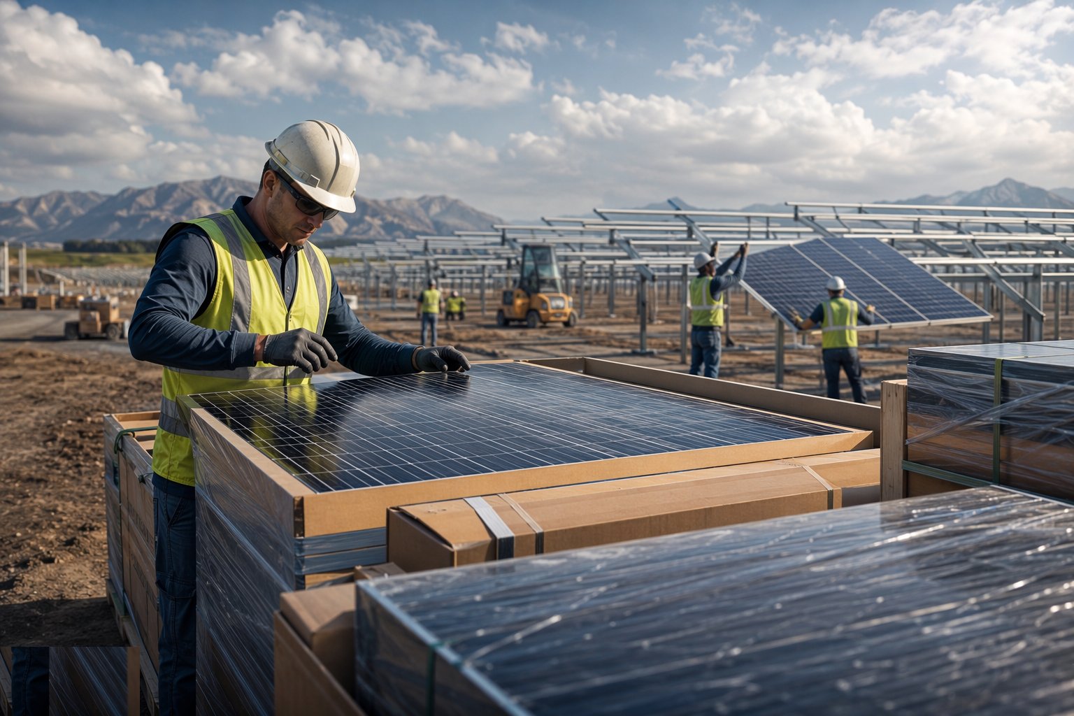
Check deliveries against the order — module type, power class and quantities — and inspect pallets for transport damage before signing for them. Run the sampling regime where specified: flash testing and, on larger schemes, electroluminescence imaging of a sample to catch cell cracks before they reach the tables. Store pallets flat, dry and out of the mud, staged by block so the distribution runs stay short and the temptation to improvise handling stays low.
Step 2: Set out and hang the first-row benchmark
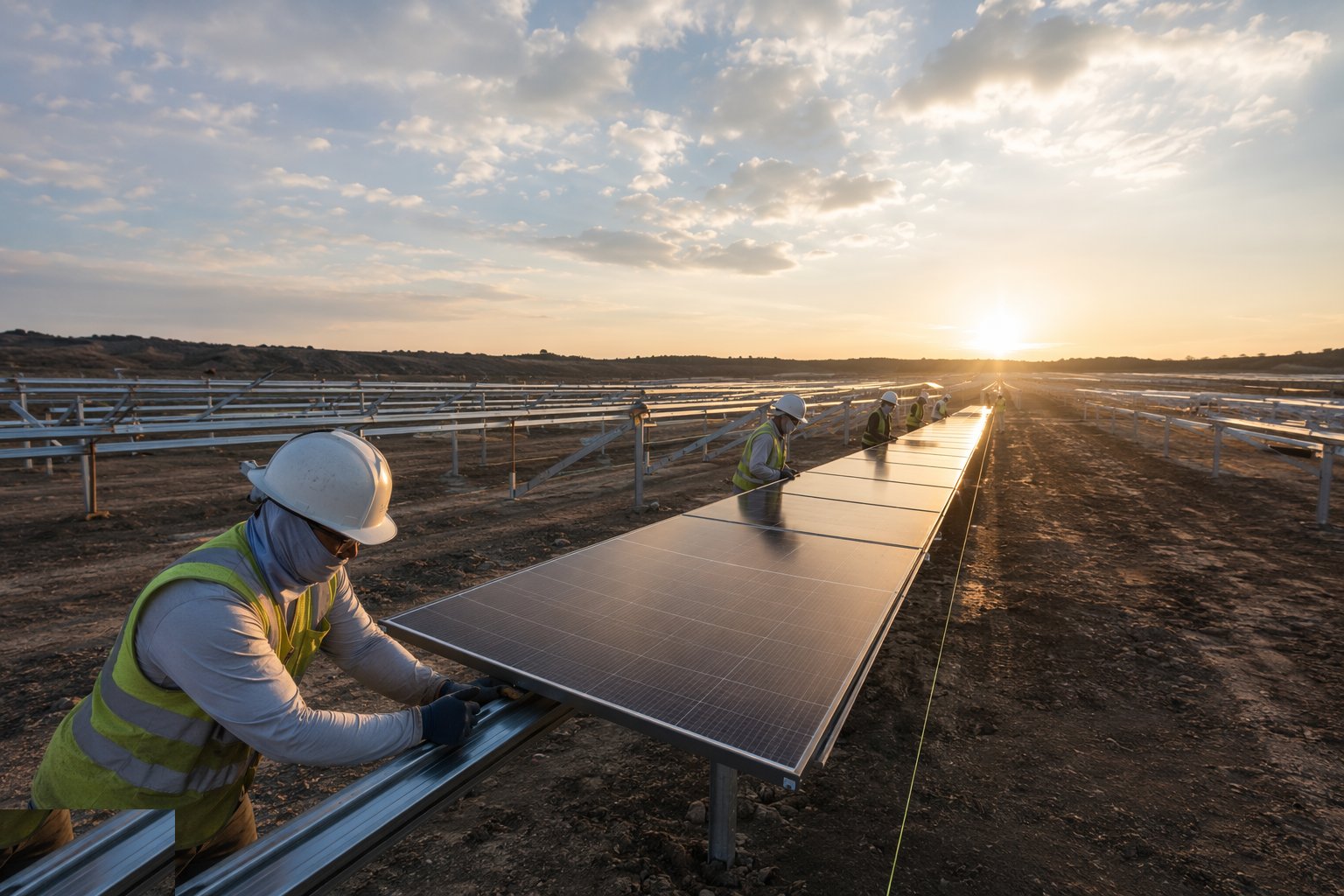
Hang the first table of each block to the full standard — clamp positions verified against the manufacturer's zones, torques applied and marked, gaps and alignment measured, wiring loomed — and have it signed off as the benchmark the production gangs copy. This is where the method is proven and the output rate is established; a benchmark table that takes all day is a programme problem identified early, which is exactly when you want it identified.
Step 3: Production hanging with handling discipline
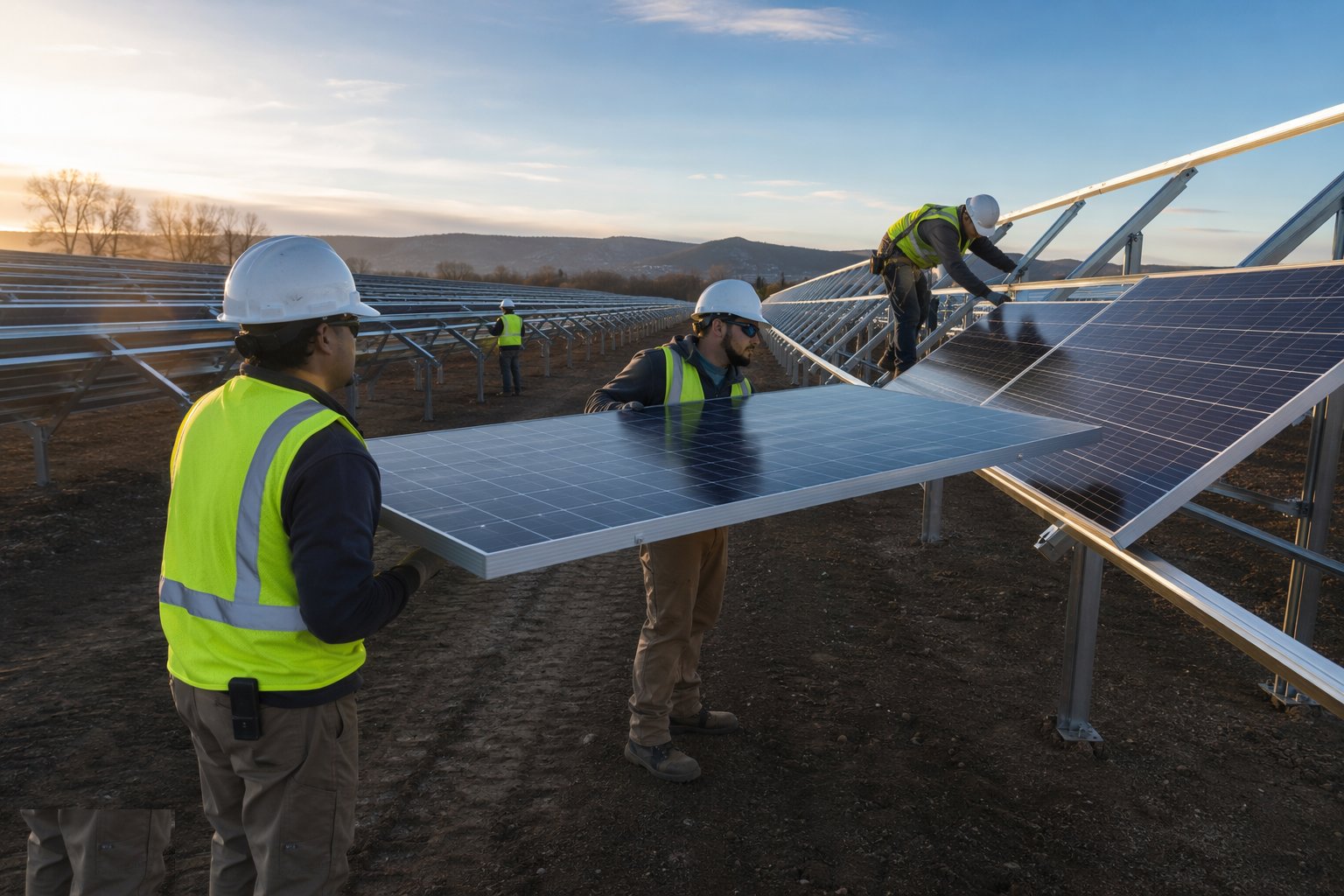
Run the gangs table by table: modules lifted per the handling rules, seated in the clamps, torqued to spec and marked. Supervise the rate against the quality checks — clamp zone compliance sampled daily, torque audits per gang, frame and glass condition as they go up. Enforce the weather rules: wind limits for hanging, and no partly-clamped modules left unsecured at the end of a shift — every module either clamped to torque or back on the pallet.
Step 4: Wire the strings and manage polarity
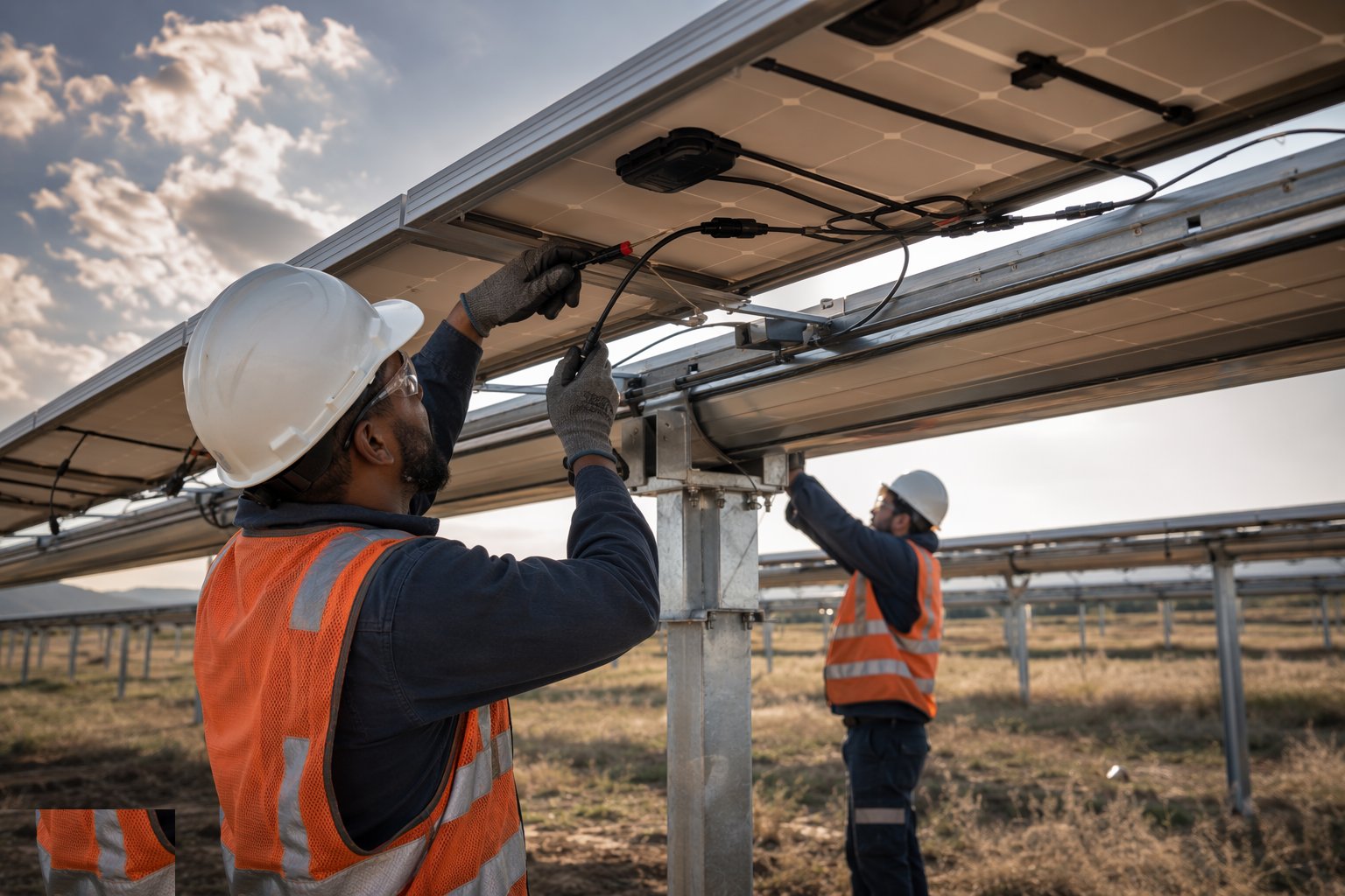
Wire strings per the stringing diagram: home runs loomed along the structure in UV-stable clips, clear of edges and off the ground, with connectors crimped using the manufacturer's tooling and matched connector pairs — mixed connector brands mated together are a fire-risk defect, not a compatibility quibble. Label every string both ends, and keep the DC isolators open and locked: strings are live in daylight, so the wiring sequence keeps the field safe until the electrical stage takes over.
Step 5: Bond the frames and complete earthing continuity
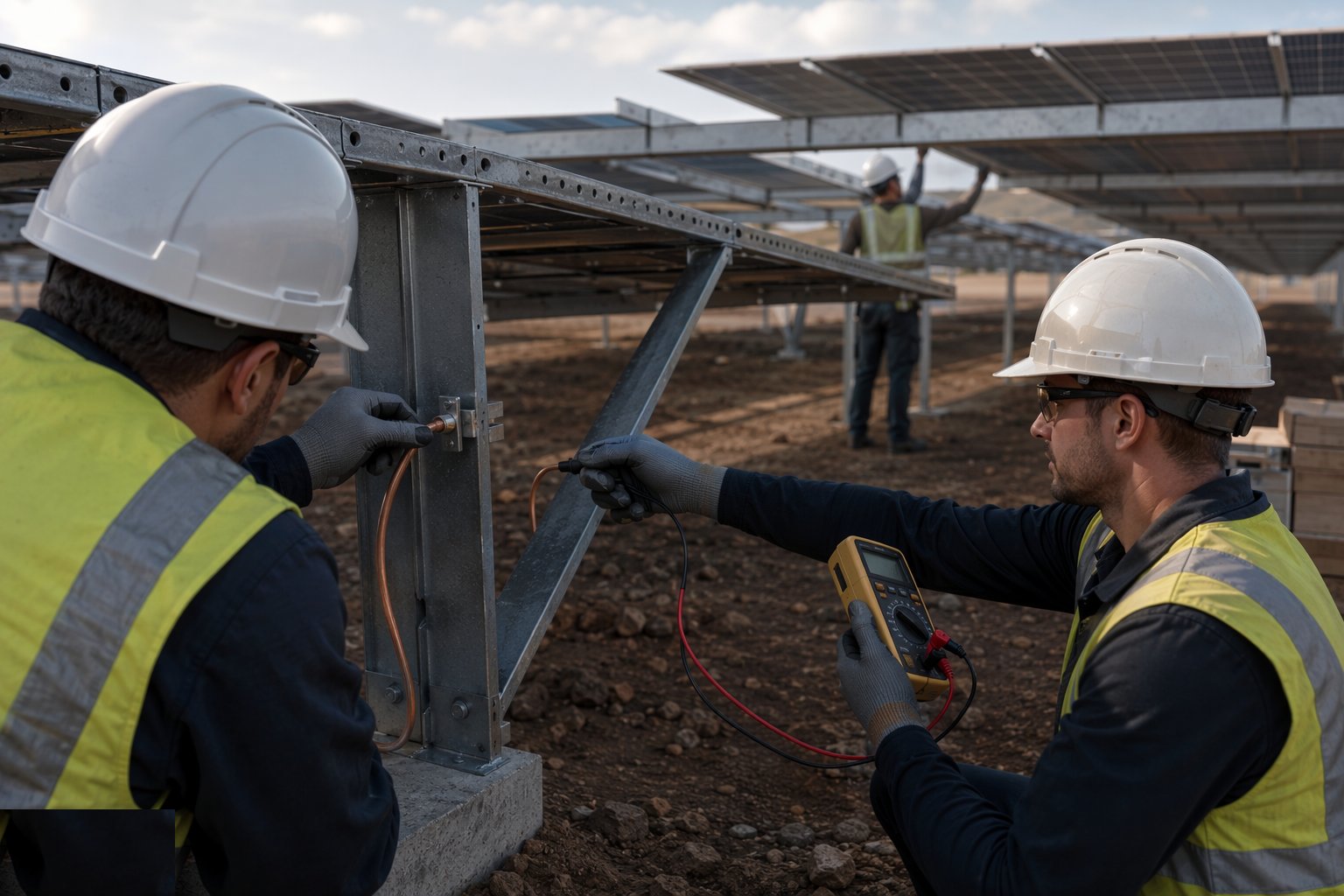
Verify the bonding path from every module frame through the racking to the structure earth: integrated bonding clamps bite the anodising or coating as designed, and continuity is tested table by table, not assumed. Record the test results against the table register — earthing continuity is a safety function and a lightning-protection function, and on a site of thousands of tables it only stays proven if it is recorded.
Step 6: Test strings and release to the electrical stage
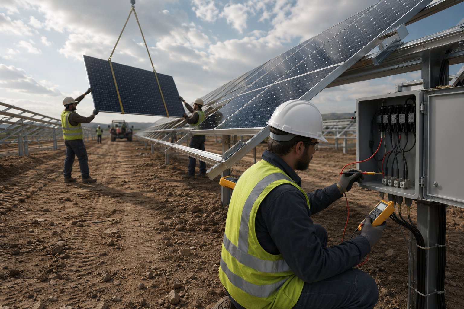
Open-circuit voltage and polarity checks on every string against the expected value for the string length and the day's irradiance — a string reading low has a fault, a disconnected module or a dead cell group, and it gets found now. Complete the string register with test values, labels and table references, clear the installation punch, and hand the DC network to the balance-of-system stage with the isolators locked and documented. The register is the commissioning document the inverter energisation will run from.
Plant and equipment
- Module handlers, vacuum lifters and telehandlers for distribution
- Torque screwdrivers and wrenches with marking systems
- Connector crimping tools matched to the connector manufacturer
- UV-stable cable ties, clips and looming materials
- Flash testers and electroluminescence imaging (sampling regimes)
- String testers: open-circuit voltage and polarity meters
- Continuity testers for frame bonding verification
- Pallet staging, stillages and block-level logistics plant
Quality control checks
- Delivery inspection and sampling results filed before hanging
- Benchmark table signed off per block before production
- Clamp-zone compliance sampled daily; torque audits per gang
- Connector pairs matched; crimps to manufacturer tooling only
- Frame bonding continuity tested and recorded per table
- String test register complete: voltage, polarity, labels
- Isolators locked open and documented until the electrical stage takes over
- Thermal gaps verified on Gulf installations at ambient extremes
Safety considerations
- Modules are sails: wind limits for hanging work, nothing left unclamped
- Strings live in daylight — locked isolators, insulated tools, DC awareness briefings
- Manual handling: two-person lifts and mechanical aids, no shoulder carries
- Working at roof or rack height on elevated tables; edge protection and harnesses
- Heat stress and midday-break compliance on desert module campaigns
- Glass breakage: cut-glove and eye protection, broken-module quarantine
- Vehicle and pedestrian segregation in block logistics routes
Common defects
- Modules clamped outside the manufacturer's zones — load rating void
- Microcracked cells from rough handling — output degradation in service, invisible at handover
- Mixed connector brands mated — overheating joints and a fire risk
- Under-torqued clamps — modules slip or lift in the first storm
- Home runs touching sharp edges or lying in water — insulation failure in years, not days
- Polarity reversed on a string — found at inverter energisation, not at string test
- Frame bonding assumed, not tested — continuity broken through anodised surfaces
- Partly-clamped rows left overnight — wind damage by morning
Best suited for
- High-rate module hanging, clamping and string wiring
- Torque-controlled clamps and correctly seated connectors
- Handling discipline that protects decades of output
- The visible face of the finished solar farm
How long does PV Module Installation take?
Typical duration: Typically 3–6 months on a 50–100 MW site running multiple gangs behind the table register; gigawatt-scale Gulf plants hang modules continuously for well over a year, phased block by block into electrical completion..
Related processes
- Site Access & Enabling Works
- Survey, Ground Investigation & Resource Studies
- Piling & Mounting Structures
- Electrical Balance of System
- Grid Connection & Energisation
- Wind Turbine Foundations
- Craneage & Tower Erection
- Wind Farm Electrical Infrastructure
- Commissioning & Energisation
- River Diversion & Cofferdams
- Dam & Powerhouse Civils
- Electromechanical Installation
- Impoundment, Commissioning & Handover
- Ground-Source Heat Pumps — Homes & Villas
- Shallow Geothermal — Commercial & District Schemes
- Deep Geothermal Drilling & Wells
- Geothermal Plant, Connection & Commissioning
- Power Generation sector guide
- Utilities & Energy group