Shallow Geothermal — Commercial & District Schemes
Borehole fields under car parks, loops cast into foundation piles and shared ambient-loop networks — shallow geothermal at commercial and district scale, where thermal balance and drilling logistics rule.
Last updated 2026-07-28 by the BuildPedia Editorial Team.
What is Shallow Geothermal — Commercial & District Schemes?
Scale a ground-source system up from one house to an office block, a school or a district and the collector stops being a garden feature and becomes infrastructure. A commercial building's ground source is typically a field of tens to hundreds of vertical boreholes, commonly 100–200 m deep on spacings of five metres or more, drilled under the car park, the playing field or the building footprint before construction starts. The design question changes with the scale: one house barely dents the ground's temperature, but a field extracting or rejecting heat every day for thirty years has to be thermally balanced across the annual cycle — or oversized, or supplemented with a dry cooler or boiler — so the ground is neither slowly frozen nor slowly cooked.
Two techniques define this scale. The thermal response test (TRT) is the field measurement the design stands on: a test borehole is looped, grouted and heated at a constant rate — typically for 48 hours or more — while the loop temperatures are logged, yielding the effective ground thermal conductivity and borehole thermal resistance that the field simulation needs. Energy piles take the opposite route to finding collector capacity: they put it inside the foundations the building needs anyway. HDPE loops are fixed to the reinforcement cages of rotary bored or CFA piles before concreting, turning the pile group into a heat exchanger — the piling page covers the piles themselves, and the loop discipline is the same as any ground collector: pressure test before the cage is lowered, test again after concreting, and protect the tails until the manifold is built.
The district-scale expression is the ambient-loop or shared-loop network — sometimes called fifth-generation district heating and cooling — in which a communal borehole field circulates water at near-ground temperature around a development and every building has its own heat pump lifting or rejecting heat to and from the loop. There is no central heat source at all, and buildings can heat and cool simultaneously with the loop absorbing the difference. UK policy is pushing exactly this kind of scheme: the Energy Act 2023 brought heat networks into regulation with Ofgem as regulator and provides for heat network zoning in England, under which zones can be designated where connection to a network is expected or required. The technical benchmark remains the CIBSE/ADE Code of Practice CP1 (2020), with the Heat Network Technical Assurance Scheme (HNTAS) being phased in to turn technical standards into mandatory, certificated ones. In the UAE the model fights the same physics as the domestic case — warm ground and one-way cooling loads — and the district analogue already exists in the chilled-water networks of Empower, Emicool and Tabreed; ground-coupled schemes in the Gulf remain demonstration-scale.
When and why is Shallow Geothermal — Commercial & District Schemes used?
The borehole field or the energy-pile loops sit at the very front of the programme — before the car park is surfaced, and literally inside the piling programme where the loops are in the foundations — with the energy centre following within the MEP works. It matters because this stage fixes the building's energy performance for its whole life: an undersized or thermally unbalanced field degrades year on year and cannot be extended once the car park is tarmacked and the building occupied, so the TRT, the annual balance simulation and the drilling QA are where the asset is actually made — the heat pumps can always be replaced, the field cannot.
Types of Shallow Geothermal — Commercial & District Schemes
Borehole fields
Arrays of vertical closed-loop boreholes drilled on a grid under car parks, landscaping or the building footprint, headered in trenches back to manifold chambers. The workhorse of commercial ground-source: scalable to hundreds of boreholes, independent of the foundations, but land-hungry in plan and utterly dependent on the TRT and the annual balance model for its sizing.
Energy piles
Foundation piles carrying heat-exchanger loops fixed to their reinforcement cages, so the substructure doubles as the ground collector. Rotary bored piles accept looped cages readily; in CFA piles the cage and loops must be placed into fresh concrete within its workable time. No extra drilling land is needed, but the loops inherit every risk of the piling operation — cage handling, concreting and trimming — and a dead loop mid-array is usually unrecoverable.
Aquifer thermal energy storage (ATES)
Paired wells storing warm and cool water in a permeable aquifer between seasons — summer heat banked underground and withdrawn in winter, and vice versa. Very efficient for large buildings with genuinely balanced loads, but wholly dependent on the right hydrogeology, and in England it carries Environment Agency abstraction and discharge licensing with ongoing monitoring duties.
Shared ambient-loop networks
A communal ground array circulating near-ground-temperature water around a development, with individual heat pumps in each building — fifth-generation district heating and cooling. Buildings can take or reject heat independently, the loop averages their diversity, and there is no central generation plant to build or man. Increasingly the policy-favoured pattern for new UK developments in heat network zones.
Shallow Geothermal — Commercial & District Schemes: step by step
Step 1: Model the annual thermal balance
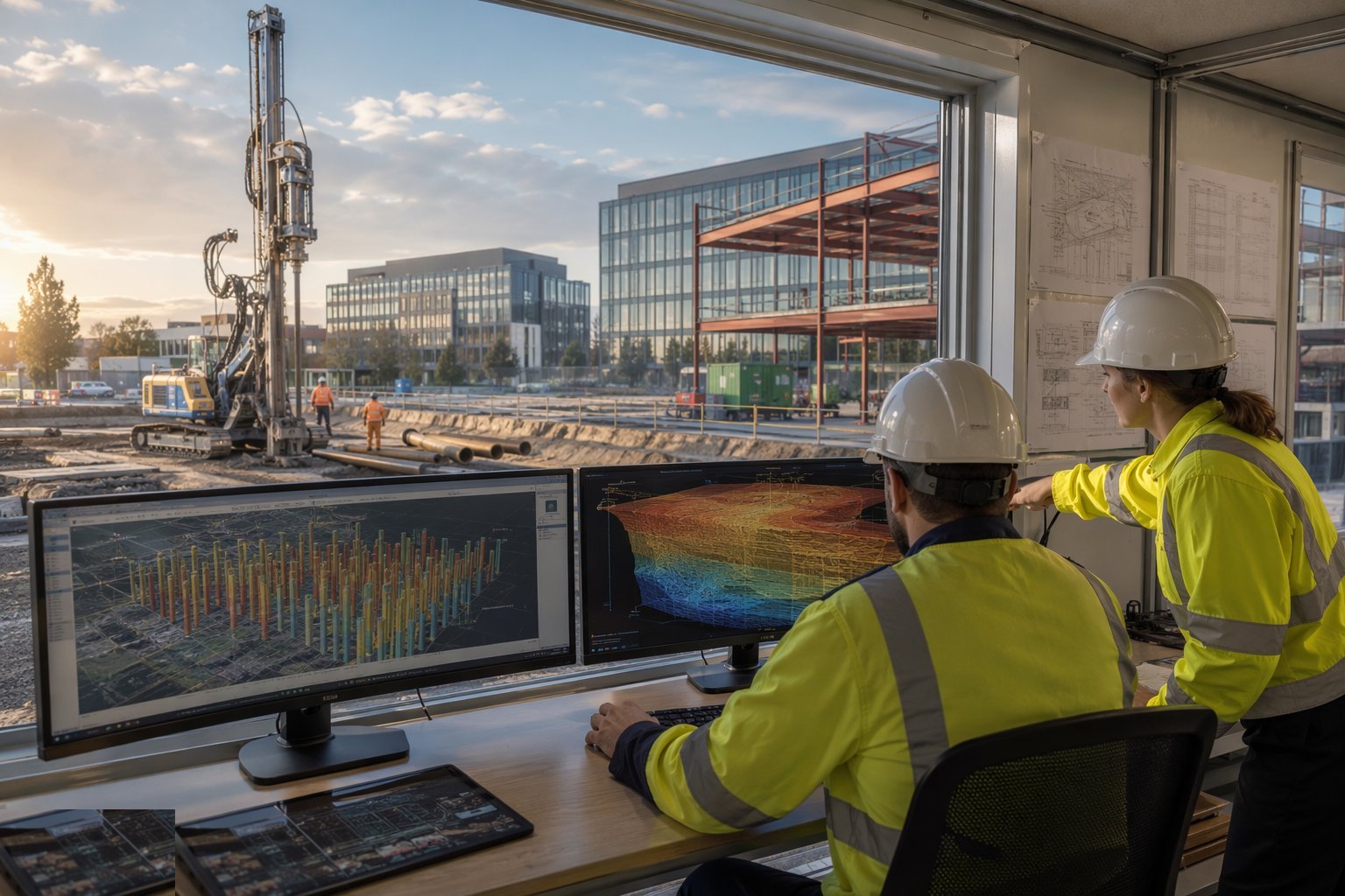
Build an hourly energy model of the building or network loads and simulate the ground's response over the design life — typically 25 years or more. The output is not just collector size but the annual extraction and rejection totals, which must roughly balance; a cooling-dominated building rejecting heat all year needs supplemental rejection (a dry cooler sized for the imbalance) or a larger field, and a heating-dominated one the reverse. Fix the supplemental plant strategy now — retrofitting it after the car park is down is a different and much uglier conversation.
Step 2: Drill the test borehole and run the TRT
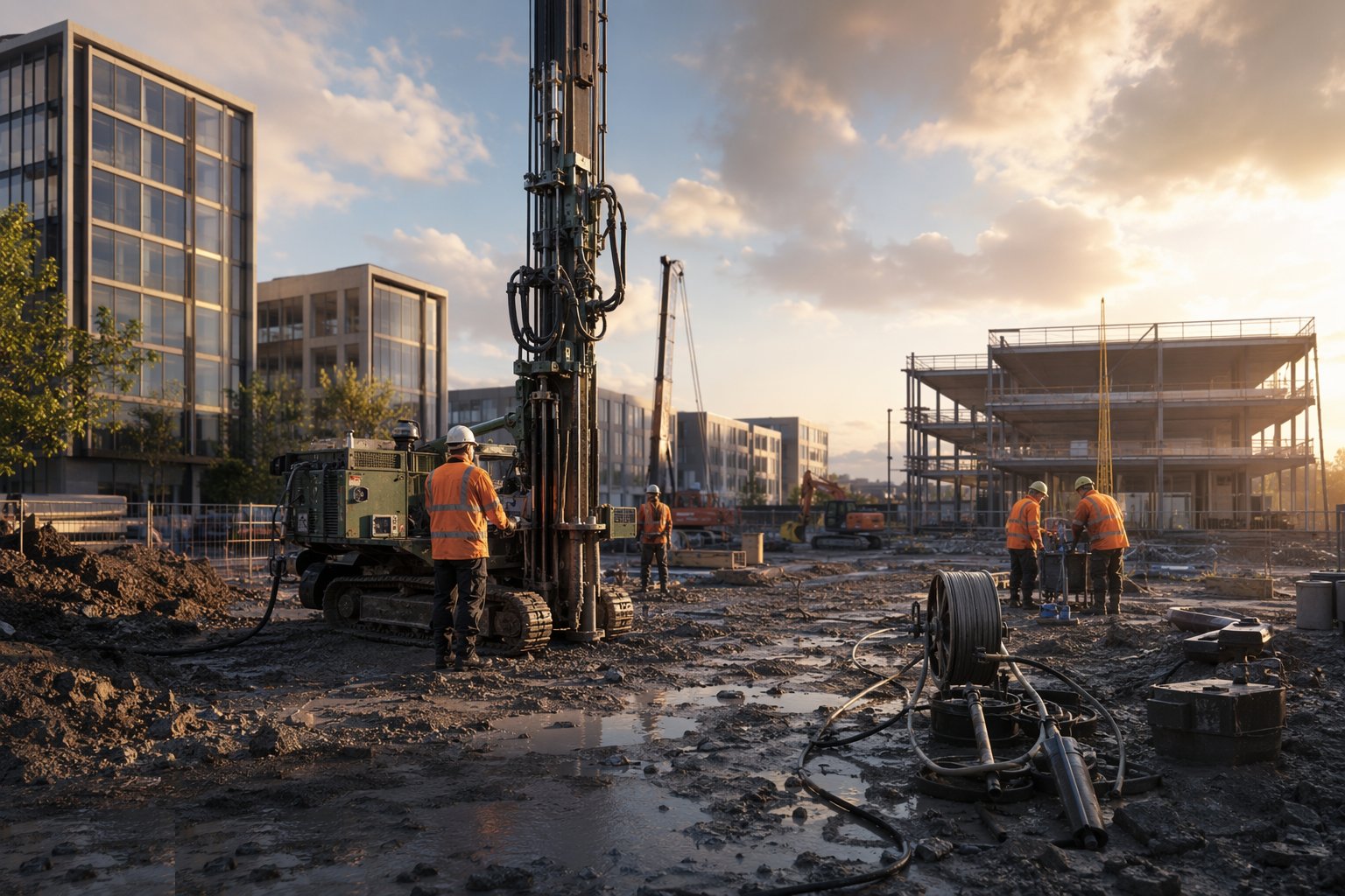
Drill at least one test borehole to the design depth, loop and grout it exactly as the production boreholes will be, and run the thermal response test — constant heat injection for typically 48 hours or more with calibrated power and temperature logging. Derive the effective ground thermal conductivity and borehole thermal resistance, and feed the measured values back into the field design. Where the TRT disagrees with the desk study, believe the TRT and resize: the whole field design is only as good as this test.
Step 3: Design the field, headers and manifolds
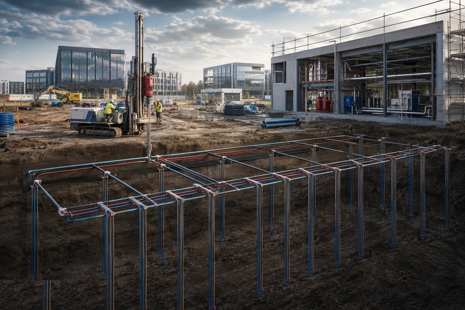
Fix the borehole count, depth and spacing — commonly five metres or more between boreholes to limit thermal interference over the field's life — and the header network: buried HDPE headers in trenches to manifold chambers, with isolation and balancing valves so every circuit can be commissioned and, later, isolated for repair. Hydraulics matter as much as heat transfer here: an unbalanced field runs a few boreholes hard while the rest idle, and the effective collector shrinks to the working fraction.
Step 4: Drill and complete the field
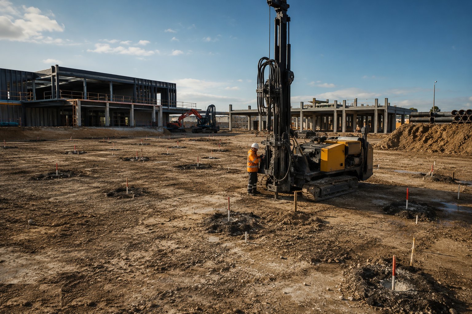
Run the production drilling campaign on the surveyed grid: drill, insert loops, grout bottom-up with thermal grout, witness returns, cap and mark every borehole, and keep the drilling platform and haul routes clean of grout and mud. Header the boreholes into the trenches as sections complete. For energy piles, the loops go in with the piling: fix them to the cages with adequate ties, pressure test before lowering and again after concreting and trimming, and protect the tails through every following trade until the manifold is built — the piling sequence and tolerances are those of the piling page, with the loop tests added to its QA.
Step 5: Pressure test, flush and fill
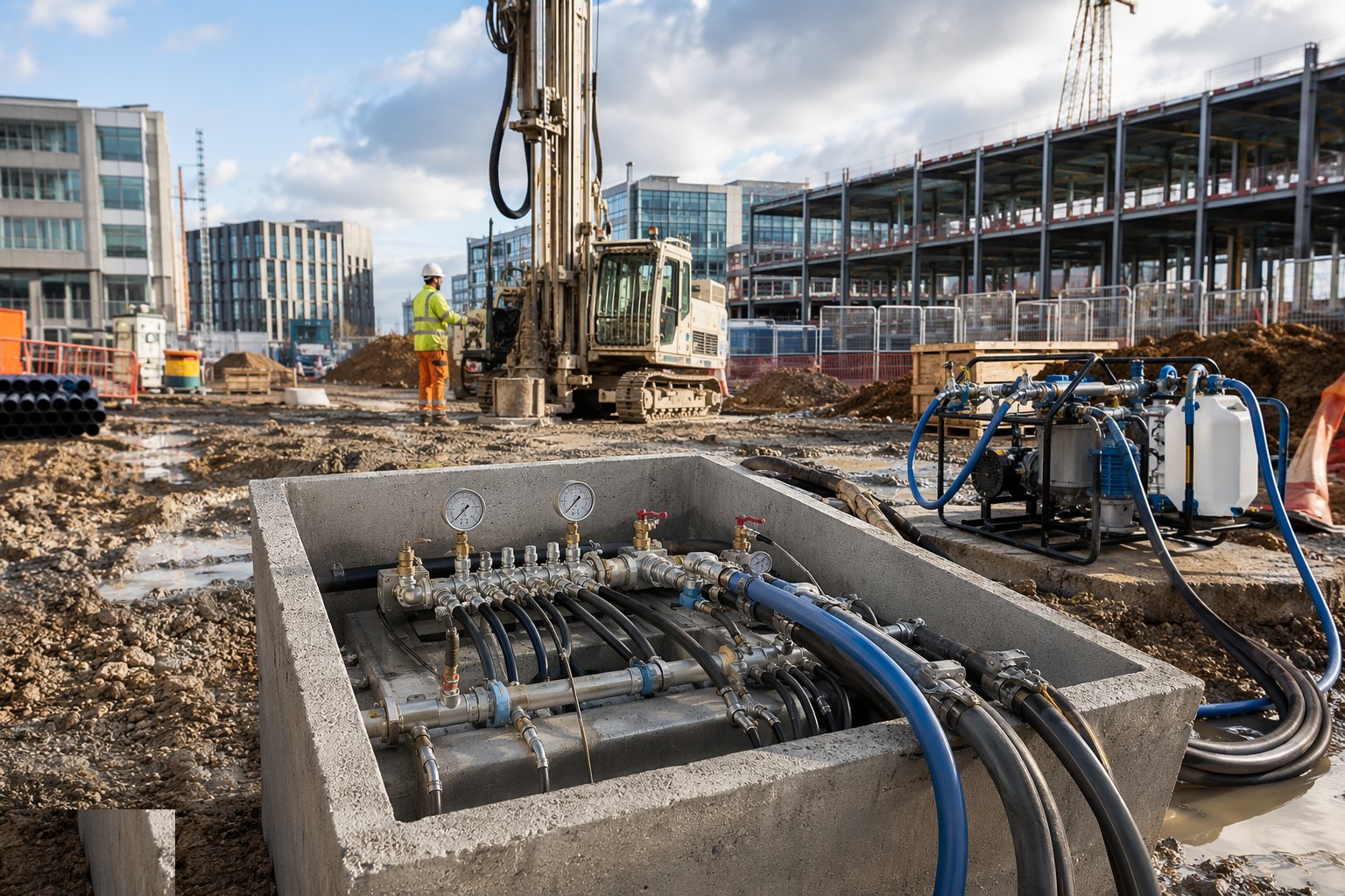
Test every circuit to the manufacturer's procedure as it is completed and again at handover — records for each borehole, each header section, each energy pile. Flush the whole field through filtration until clear and air-free, fill with the specified antifreeze mixture, dose any treatment chemicals and verify concentrations with a refractometer. Set and record the balancing valve positions circuit by circuit.
Step 6: Build the energy centre or the loop connections
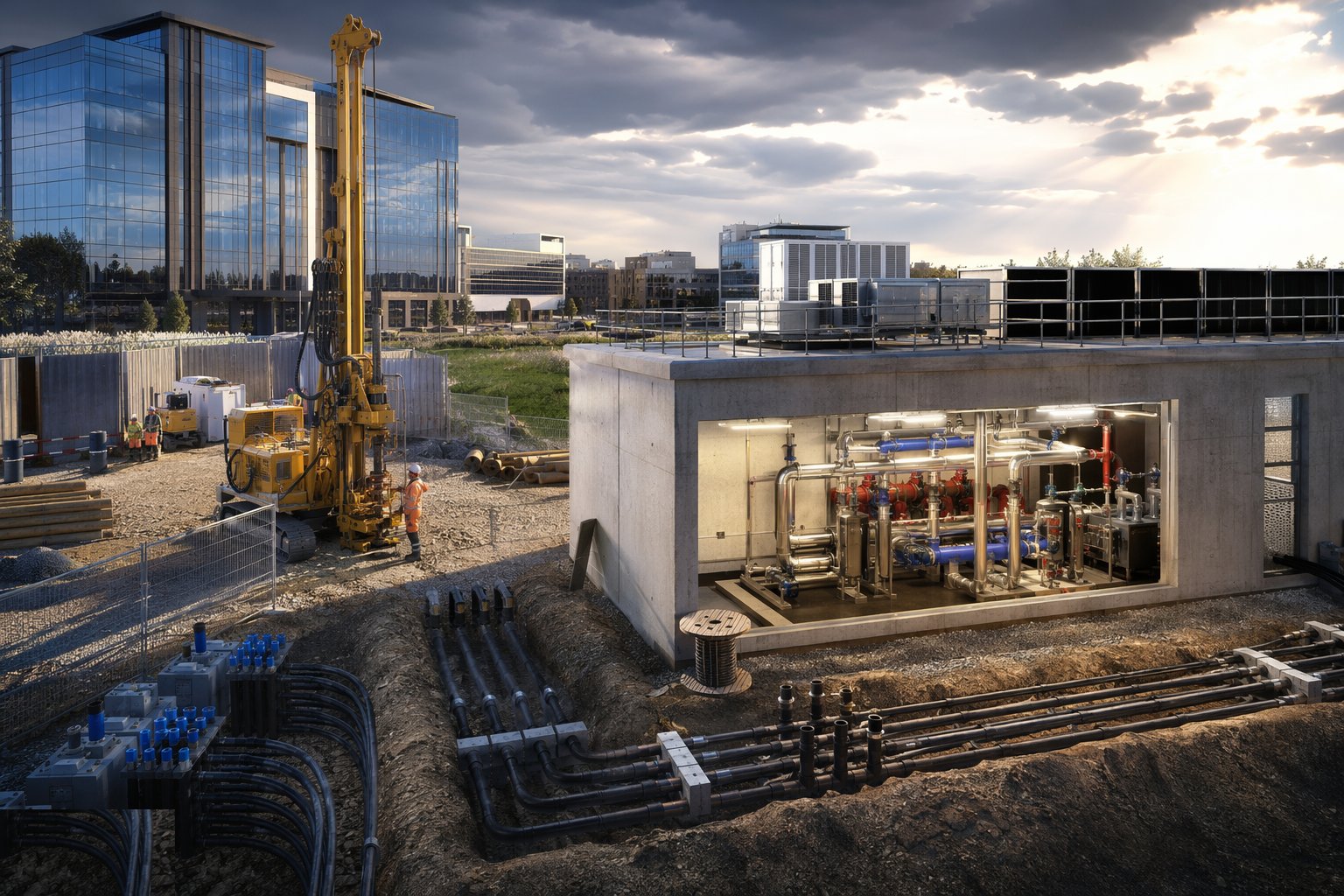
For a central scheme, install the heat pump cascade — headered units with plate heat exchangers separating ground-side and building-side water — the pumps, pressurisation, controls and heat metering. For an ambient-loop network, the central work is the loop itself, the pumping and the connection points; each building's heat pump is installed with its own fit-out. Either way, metering and controls go in now, because the network's performance claims and its regulatory duties will be evidenced from this data.
Step 7: Commission the field and network and hand over
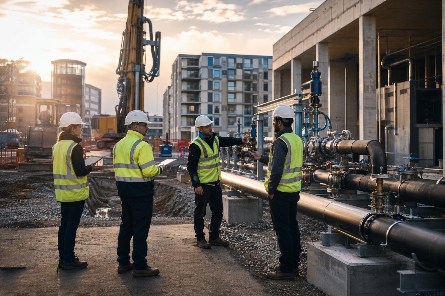
Commission hydraulically and thermally: flows balanced across every circuit, the field's overall flow and temperature response checked against the model, heat pumps staged on and their duty points verified. Where the scheme is a heat network, structure the commissioning records to CP1 and complete the registration and notification duties the new regulatory regime requires — with HNTAS phasing in, assume certificated technical assessment is coming and build the file to survive it. Hand over the balance model, the TRT report, the as-drilled field survey and the O&M strategy as one package.
Plant and equipment
- Geothermal drilling rigs and support equipment for production borehole campaigns
- Thermal response test unit with calibrated heating and temperature logging
- HDPE pipe, U-tube probes, electrofusion and butt-fusion jointing equipment
- Thermal grout batching and pumping plant
- Flushing, filtration and glycol dosing rigs
- Manifold chambers, header pipework and balancing valves
- Central heat pump plant, plate heat exchangers, pressurisation and heat metering
- For energy piles: loop fixing and pressure test sets integrated with the piling tackle
Quality control checks
- TRT report issued and the field design revised to measured values before production drilling
- Annual thermal balance model approved, with supplemental plant triggers defined
- Every borehole logged: depth, loop type, grout returns witnessed, surveyed position
- Loop pressure tests before burying, after headering and again at handover — recorded per circuit
- Energy-pile loops tested before cage lowering and again after concreting and trimming
- Hydraulic balancing records for every circuit of the field
- Antifreeze concentration and water treatment verified and logged
- Commissioning records structured to CP1 where the scheme is a heat network
Safety considerations
- Designed and certificated rig working platforms — rigs track across the site for weeks
- Service clearance on the whole drilling grid: every position scanned before the rig moves on
- Grout and drilling-mud management — slips, spills and groundwater protection
- Confined space discipline in manifold chambers
- Hot work and fume controls on HDPE fusion jointing
- Interface management with live piling operations for energy piles — one lifting plan, one exclusion regime
- Glycol and treatment chemical handling under COSHH controls
Common defects
- Field sized from desk-study conductivity with no TRT — the whole array chronically underperforms
- Cooling-dominated field without supplemental rejection — ground temperature creeps up year on year
- Boreholes drilled too close — thermal interference short-circuits the field
- Grout shortfalls leaving an ungrouted annulus — poor heat transfer and an aquifer pathway
- Energy-pile loops damaged in cage handling or concreting — dead collectors buried mid-array
- Manifold hydraulics never balanced — the far half of the field does nothing
- Header pipework damaged by following trades and buried unrecorded
Best suited for
- Borehole fields beneath car parks and landscaping
- Energy loops cast into foundation piles
- Shared ambient-loop networks serving whole districts
- Seasonal thermal balance managed across heating and cooling
How long does Shallow Geothermal — Commercial & District Schemes take?
Typical duration: Feasibility, TRT and design typically take two to four months; production drilling of a commercial field runs four to twelve weeks depending on borehole count; energy-centre installation and commissioning follow within the building's MEP programme..
Related processes
- Dam & Powerhouse Civils
- Electromechanical Installation
- Impoundment, Commissioning & Handover
- Ground-Source Heat Pumps — Homes & Villas
- Deep Geothermal Drilling & Wells
- Geothermal Plant, Connection & Commissioning
- Site Access & Enabling Works
- Survey, Ground Investigation & Resource Studies
- Piling & Mounting Structures
- PV Module Installation
- Electrical Balance of System
- Grid Connection & Energisation
- Wind Turbine Foundations
- Craneage & Tower Erection
- Wind Farm Electrical Infrastructure
- Commissioning & Energisation
- River Diversion & Cofferdams
- Shallow Geothermal — Commercial & District Schemes in District Energy & Utility Networks
- Power Generation sector guide
- Utilities & Energy group