Wind Turbine Foundations
The reinforced concrete bases that hold a 100-metre-plus tower against the overturning pull of the rotor — built to millimetre-level bolt tolerances at the end of a moorland track.
Last updated 2026-07-28 by the BuildPedia Editorial Team.
What is Wind Turbine Foundations?
A wind turbine is a very tall cantilever with a very large sail on top. The rotor catches the wind and the tower transmits the loads down as an overturning moment, and the foundation's job is to take that moment into the ground without moving — not just once, but through millions of load cycles over a 25-year-plus life. Onshore, the foundation is almost always a reinforced concrete base, commonly 15 to 20 metres across and several metres deep, with a few hundred cubic metres of concrete poured in a single continuous operation. The part that makes turbine foundations different from ordinary bases is the anchor cage: a steel ring assembly holding the circle of bolts that the tower's bottom flange will bolt directly to. That ring is cast into the concrete, and its level and position are surveyed to millimetre-level tolerances set by the turbine supplier — because if the cage is wrong, the tower simply will not bolt up, and there is no site fix for that.
The foundation type comes straight out of the ground investigation. Where competent ground sits at workable depth, a gravity (spread) foundation is the default: mass and geometry do the work. Over soft ground, deep peat or variable ground the base sits on a group of piles with a pile cap; over shallow sound rock, a rock-anchored foundation post-tensions a slimmer cap to the rock with ground anchors. Offshore is a different world entirely — single large-diameter steel monopiles driven or drilled into the seabed and topped with transition pieces carrying the access platforms — but the principle is identical: fix the tower to the ground so it cannot rotate.
In the UK these foundations are built on moors and hills, so the practical battles are weather, haulage of ready-mixed concrete along single-track access roads, and peat. Mass concrete pours of this size need thermal control — the core heats as it hydrates and the surface-to-core temperature difference has to be managed to avoid cracking. In the Gulf, utility-scale wind is the exception rather than the rule — solar dominates the regional mix, and the reference scheme is Oman's Dhofar wind farm rather than anything in the Emirates themselves — but where wind is built in hot climates, the same hot-weather concreting discipline applies as everywhere else in the Gulf: chilled mixes, tight haul times, and never retempering with water.
When and why is Wind Turbine Foundations used?
Turbine foundations come after access tracks, survey and ground investigation — the rigs and the concrete wagons have to reach each position, and the design has to be proven against real ground — and they must be poured, cured and backfilled well before the erection crane arrives, because the crane pads sit alongside them and the bolts must have full strength before any tower section lands. The stage matters out of all proportion to its appearance: an anchor cage installed out of level or out of position is a latent catastrophe that only reveals itself when a 70-tonne tower section is hanging in the air, and the foundation production rate — typically one base per week or fortnight across a season — sets the rhythm for every trade that follows. At the small end, a farm or domestic turbine of a few tens of kilowatts stands on the same kind of gravity base shrunk to tens of cubic metres, cast in one pour with an anchor frame or holding-down bolts surveyed level — the overturning physics does not scale down, so neither does the survey discipline.
Types of Wind Turbine Foundations
Gravity (spread) foundation
A shallow inverted-cone or slab-and-plinth reinforced concrete base that resists overturning through its own weight and footprint. It is the default where competent ground is found at workable depth, and it is usually the largest single concrete pour on the project — commonly several hundred cubic metres in one continuous operation.
Piled foundation
A group of bored or driven piles capped by a reinforced concrete pile cap carrying the anchor cage. Used over soft ground, deep peat or variable ground where a spread base would settle or rotate; the piling itself follows the same working-platform and testing discipline as any deep foundation.
Rock-anchored foundation
A slimmer concrete cap post-tensioned down to sound rock with drilled ground anchors. Attractive where shallow rock would otherwise mean blasting out a full-size gravity excavation, but wholly dependent on anchor drilling, grouting and testing quality.
Offshore monopile and transition piece
A single large-diameter steel tube driven or drilled into the seabed, topped by a transition piece carrying the boat landing, platform and cable entry. A marine piling operation with its own vessels, hammers and weather windows — the same structural idea as the onshore base, executed at sea.
Wind Turbine Foundations: step by step
Step 1: Confirm the design and re-survey the position
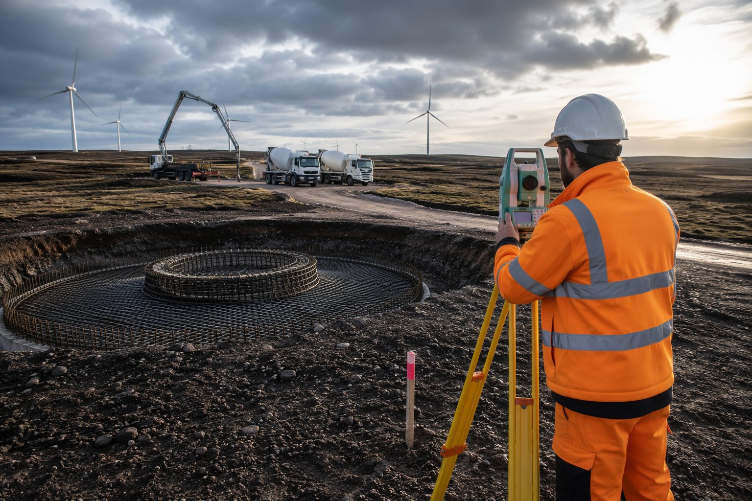
Before any excavation, check the foundation design against the interpretative ground investigation report for that specific position — bearing, settlement and, for piled or anchored solutions, the pile or anchor design. Re-survey the turbine position from the site control network and confirm there is no clash with cable routes, tracks or drainage. This is a hold point: the position and design confirmation are signed off before formation is broken.
Step 2: Excavate to formation and blind
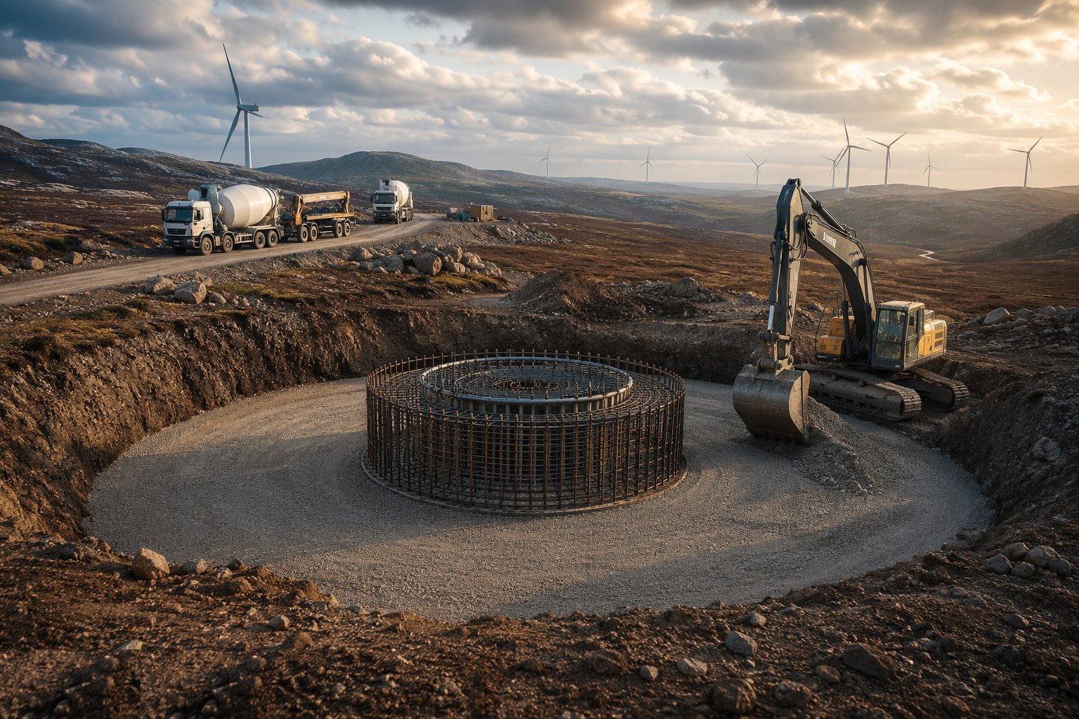
Excavate to the design formation level, supporting or battering the sides as the ground requires, and keep the base dry — sumps and pumps for the life of the excavation. Inspect and approve the formation: soft spots, disturbed material and loose arisings come out and are replaced with blinding or mass concrete. Cast the blinding layer to give a clean, level working surface, and set out the anchor cage centre and bolt circle onto it.
Step 3: Assemble and survey the anchor cage
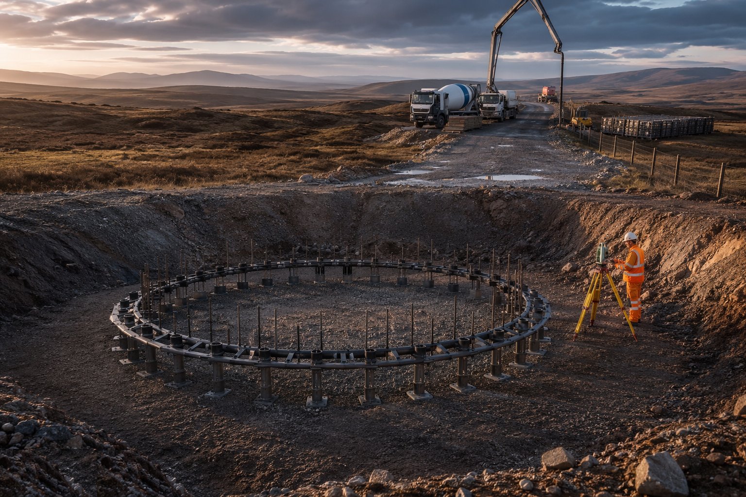
The anchor cage arrives in sections and is assembled on its template or support stools, with the bolt ring levelled on adjustable legs. This is the tolerance-critical operation of the whole foundation: survey the top ring for level and position to the turbine supplier's tolerance — millimetre-level, not centimetre-level — and lock it off so the pour cannot move it. Protect every bolt thread with caps or grease-and-wrap, and re-survey the cage during and immediately after concreting.
Step 4: Fix reinforcement, ducts and earthing
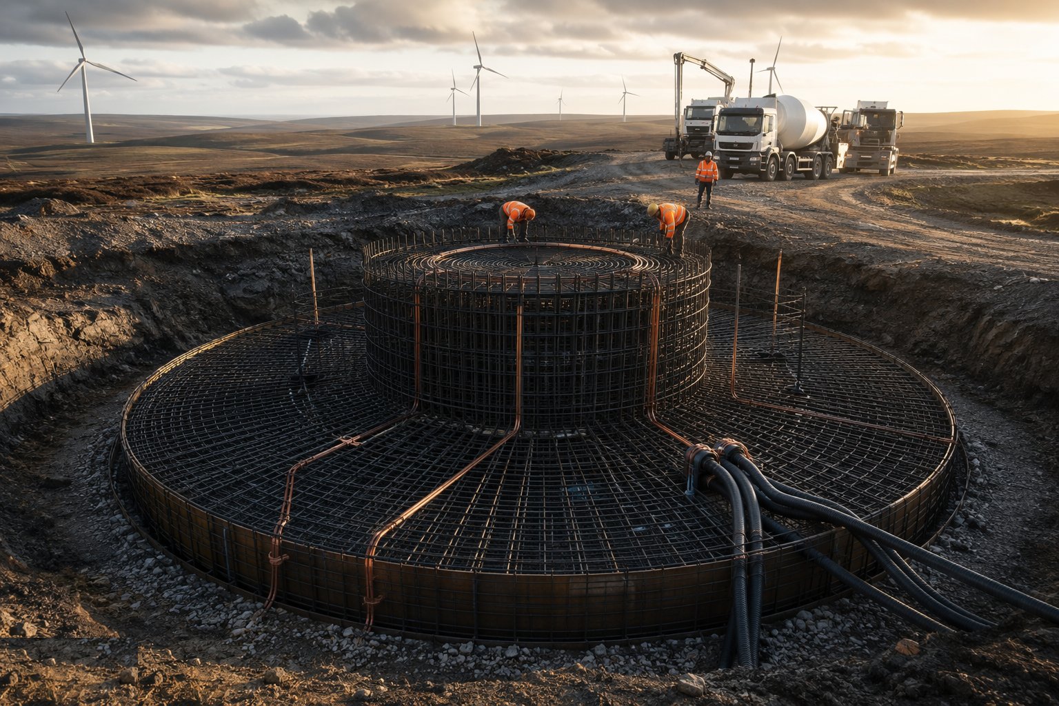
Fix the reinforcement cage around and through the anchor cage to the bending schedules, with spacers and chairs holding cover — congested around the bolt ring, so check the poker vibrators can still reach. Lay in the cable ducts from the trench route, the earthing connections to the site earth grid, and any instrument or drainage details. The pre-pour inspection against the ITP is a hold point: reinforcement, cage survey, ducts and cover are all signed off before concrete is ordered.
Step 5: Pour the concrete in one continuous operation
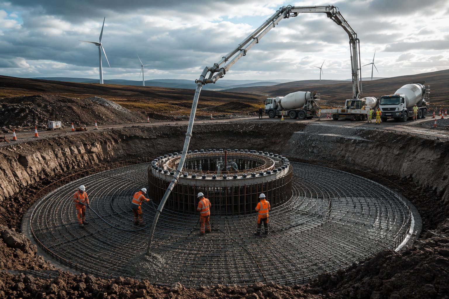
Turbine bases are poured continuously — a cold joint through the bolt circle is not acceptable — so the ready-mixed supply chain is planned like a military operation, often drawing on more than one batching plant with a defined pour rate and backup. Place by pump, vibrate thoroughly around the cage, and take the specified cubes for strength verification. For these mass pours, monitor the temperature differential between core and surface and manage curing accordingly; in hot climates apply the full hot-weather concreting discipline — chilled mix water or ice, shaded aggregates, tight haul times, no retempering.
Step 6: Cure, strike and backfill
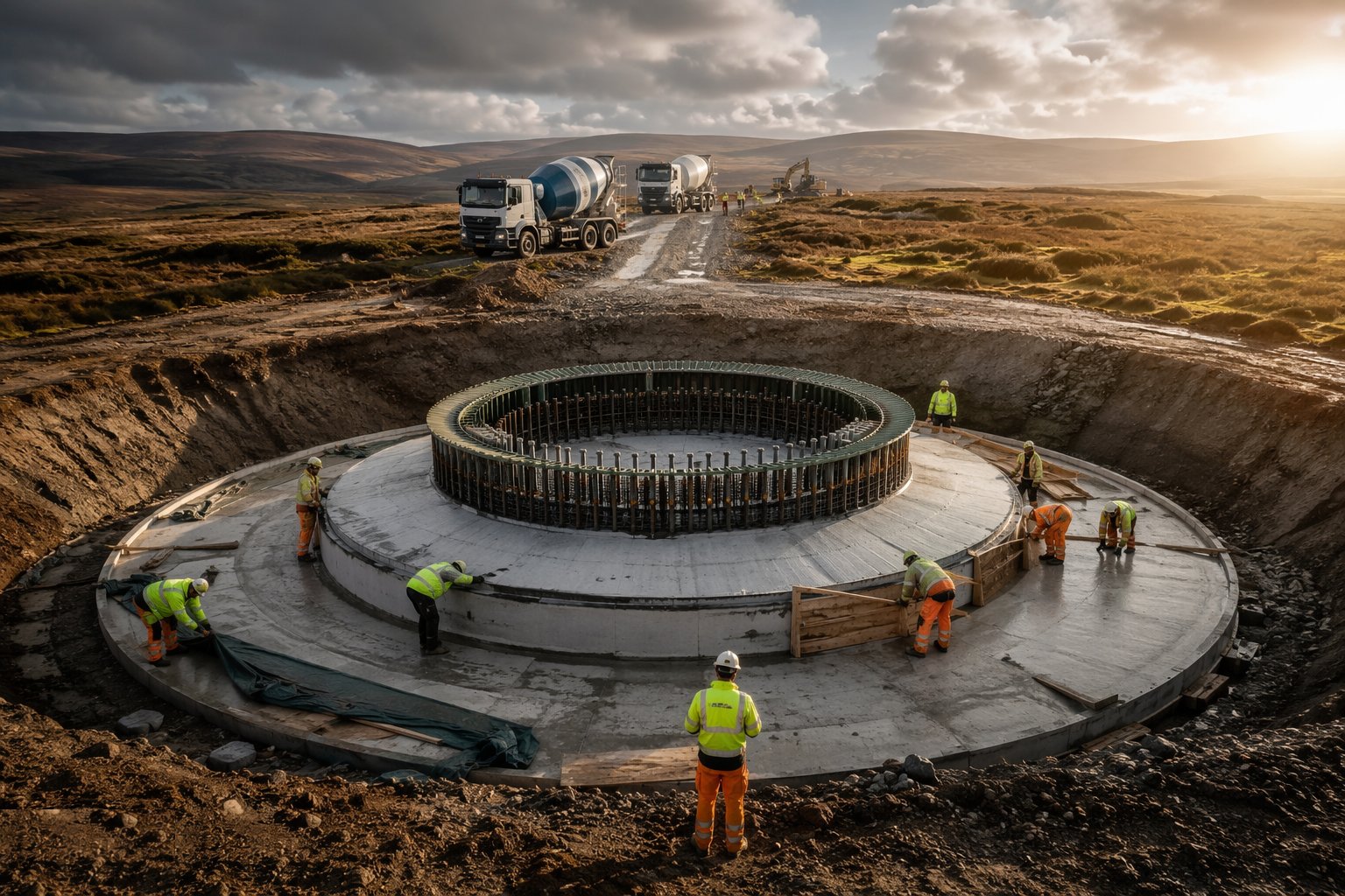
Cure the base to the specification — hessian and water, curing membrane or insulated blankets where thermal control demands it — and strike formwork only when the verified strength allows, not by calendar. Backfill around the base in compacted layers so the completed formation can take erection-stage loads, and finish the hardstand around the foundation to its own design. The bolts stay greased, capped and protected from now until the tower arrives.
Step 7: Verify, document and hand over
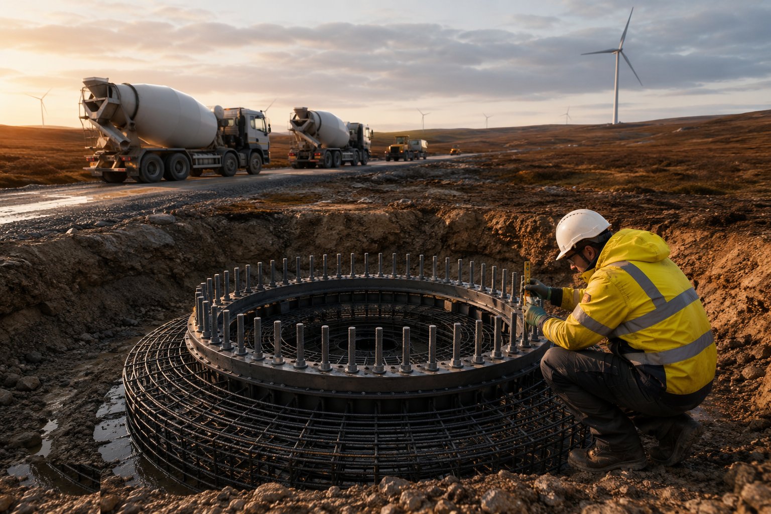
Close the foundation with an as-built survey of the anchor cage — bolt circle position, level and protrusion — filed against the supplier's tolerances, plus the cube results, pour records and thermal monitoring. Raise NCRs and agree remedies for anything out of tolerance now, not when the tower is delivered. The completed foundation, its records and the adjacent certified crane pad are handed to the erection team as one package.
Plant and equipment
- 360° excavators, dozers and compaction plant for excavation and backfill
- Truck mixers, concrete pumps and batching plant capacity for continuous mass pours
- Anchor cage templates, support stools and adjustable levelling legs
- Total stations and precise levelling equipment for millimetre-level cage survey
- Poker vibrators and concrete skips
- Thermal probes and data loggers for mass-pour temperature monitoring
- Curing equipment — hessian, water bowsers, membranes and insulated blankets
- Piling rigs or anchor-drilling rigs where piled or rock-anchored bases are used
Quality control checks
- Formation inspected and approved before blinding — a recorded hold point
- Anchor cage surveyed before, during and after the pour against supplier tolerances
- Concrete cubes taken and tested per pour, with pour and supply records kept
- Core-to-surface temperature differential monitored on mass pours
- ITP hold points signed for reinforcement, cover, ducts and earthing before concrete
- As-built survey of the bolt circle filed and compared to tolerance
- NCRs raised and closed on any out-of-tolerance cage or concrete defect
Safety considerations
- Excavation support, battering or benching, and edge protection around every base
- Working under and around the suspended anchor cage during assembly — controlled lifts and exclusion zones
- Concrete burns — gloves, eye protection and wash-down facilities at every pour
- Plant and pedestrian segregation on congested moorland sites with limited space
- Remote-site welfare, journey management and emergency response on upland sites
- Manual handling of reinforcement — mechanical aids and team lifts
- Heat-stress management and midday-break compliance where wind is built in hot climates
Common defects
- Anchor cage out of level or position — the tower flange will not bolt up and the base may be unrecoverable
- Bolt threads damaged or unprotected during the pour and backfill
- Honeycombing around the congested cage from poor vibration access
- Thermal cracking from an unmanaged core-to-surface temperature differential
- Cold joints where the continuous pour was interrupted by supply failure
- Cable ducts blocked, misaligned or cast in at the wrong angle
- Backfill placed without compaction control — settlement under the hardstand later
Best suited for
- Gravity bases holding a 100-metre tower against overturning
- Bolt-ring and anchor tolerances measured in millimetres
- Mass concrete pours at the end of a remote access track
- Thermal and curing control on single large-volume pours
How long does Wind Turbine Foundations take?
Typical duration: Commonly 3–6 weeks per foundation from excavation to cured, backfilled handover, including strength gain; a fleet of 15–25 bases typically pours at a rate of one per week to one per fortnight through the working season, weather and concrete supply permitting..
Related processes
- Piling & Mounting Structures
- PV Module Installation
- Electrical Balance of System
- Grid Connection & Energisation
- Craneage & Tower Erection
- Wind Farm Electrical Infrastructure
- Commissioning & Energisation
- River Diversion & Cofferdams
- Dam & Powerhouse Civils
- Electromechanical Installation
- Impoundment, Commissioning & Handover
- Ground-Source Heat Pumps — Homes & Villas
- Site Access & Enabling Works
- Survey, Ground Investigation & Resource Studies
- Shallow Geothermal — Commercial & District Schemes
- Deep Geothermal Drilling & Wells
- Geothermal Plant, Connection & Commissioning
- Power Generation sector guide
- Utilities & Energy group