Electromechanical Installation
Turbines, generators, governors and the switchyard — the rotating heart of the scheme, assembled to machining tolerances inside the concrete shell the civils have handed over.
Last updated 2026-07-28 by the BuildPedia Editorial Team.
What is Electromechanical Installation?
The turbine is chosen by the water, not by preference. The head and flow of the site pick the machine: as a rough guide, Pelton turbines — jets driving a bucketed wheel — suit high heads and smaller flows, typically from a couple of hundred metres of head upward; Francis turbines cover the broad middle ground, roughly from tens of metres to several hundred; and Kaplan turbines — propeller machines with adjustable blades — suit low heads and large flows, typically below about forty metres. The ranges overlap, and the final selection is a model-tested engineering decision, but the geography of the valley has usually made the choice before the tender goes out.
Installation happens inside the concrete the civils have built, and its governing discipline is alignment. The draft-tube liner, stay ring and spiral case are set to the machine datum and surveyed; the civils then embed them in concrete under monitoring, because a spiral case that distorts during its embedment pour is a permanent defect in the heart of the station. On that foundation the turbine is assembled — wicket gates, runner, shaft and bearings — then the generator above it: stator stacked and wound in situ on larger machines, the rotor spider, rim and poles built up piece by piece, and the air gap between them measured and adjusted to fractions of a millimetre. This is heavy engineering with watchmaker's tolerances, executed with the powerhouse overhead crane as the indispensable third hand.
Around the machines sit the systems that control and connect them: the governor and its hydraulic oil system regulating the wicket gates, the cooling water and fire systems, the penstock valves, and the switchyard with its transformers and switchgear feeding the grid. Pumped storage adds a dimension — reversible pump-turbines that generate by night's stored water and pump back when power is cheap or abundant. The Gulf's reference is DEWA's Hatta scheme: 250 MW of reversible plant linked by a reported 1.2-kilometre tunnel between upper and lower reservoirs, designed to respond to the grid in around ninety seconds and to store solar generation from the Mohammed bin Rashid Al Maktoum Solar Park.
When and why is Electromechanical Installation used?
Electromechanical installation follows the powerhouse civils — it cannot finally set a component until the embedments, pits and machine hall are handed over to datum tolerance — and it overlaps them heavily, because the powerhouse crane, the draft-tube liners and the spiral cases are themselves needed by the civils as they close the structure around the machines. It matters because every subsequent performance and warranty claim traces back to this work: alignment, air gaps and embedment stability decide vibration, efficiency and bearing life for decades, and the interface records made here — surveys, torque records, test certificates — are the baseline the commissioning phase and the decennial-scale liability arguments will stand on. Micro-hydro schemes set their machines the same way: a compact turbine or an Archimedean screw landed by a mobile crane, aligned to its datum and grouted, with the alignment records just as load-bearing at 50 kW as at 50 MW — vibration does not read the nameplate.
Types of Electromechanical Installation
Francis turbine
A reaction turbine with water spiralling inward through a scroll case and wicket gates onto a mixed-flow runner. The workhorse of the industry across medium heads and the widest range of outputs — most conventional hydro stations in the world run Francis machines.
Kaplan turbine
A propeller-type reaction turbine with adjustable runner blades and wicket gates, keeping efficiency high across varying low-head flows — with bulb and pit variants for the lowest heads. The choice for run-of-river schemes on big, flat rivers.
Pelton turbine
An impulse turbine where high-pressure jets strike bucketed runners in free air — no submerged casing, simple in principle, superb at high heads with smaller flows. The machine of mountain schemes, where the penstock pressure does the work.
Reversible pump-turbine (pumped storage)
A Francis-type machine that generates in one direction of rotation and pumps in the other, paired with a motor-generator. The defining plant of pumped-storage schemes such as Hatta — two reservoirs, one machine hall, and a grid-scale battery made of water.
Electromechanical Installation: step by step
Step 1: Accept the civil handover and set the datums
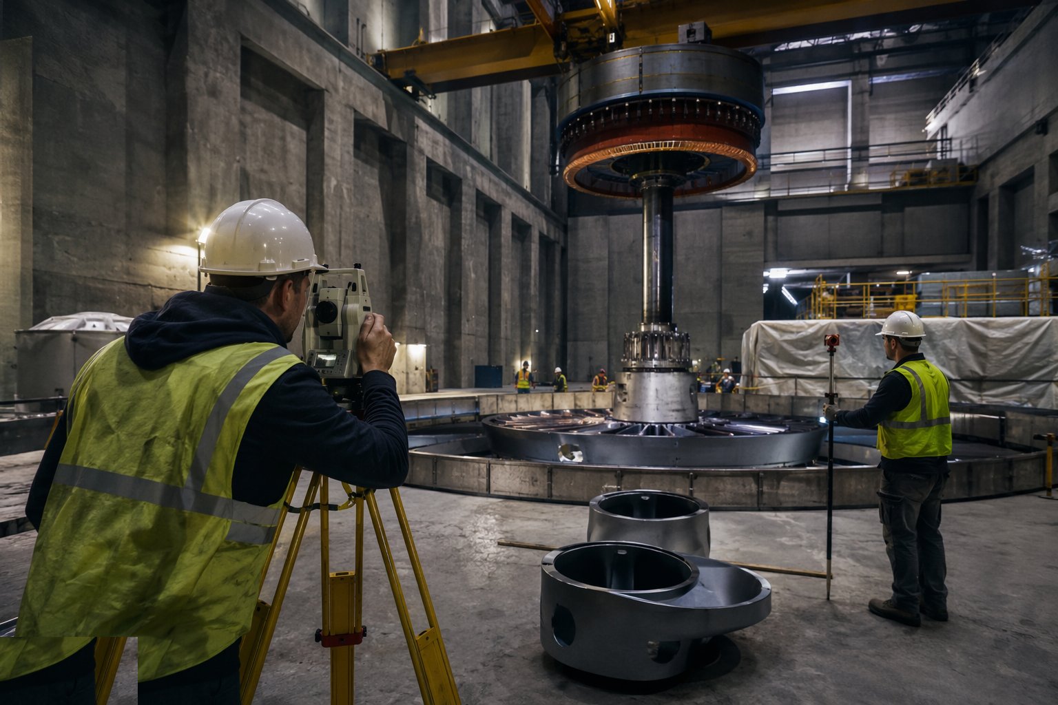
Start with a formal dimensional handover: the machine axis and elevation datums re-established from site control, and the embedments — sole plates, anchor bolts, pit geometry — surveyed against the supplier's tolerances. Discrepancies are resolved with the civils now, by grinding, shimming or agreed modification, not discovered at machine assembly. Commission and load-test the powerhouse overhead crane first — it is the installation's primary tool, and its certification is an early milestone in its own right.
Step 2: Set the draft-tube liner, stay ring and spiral case
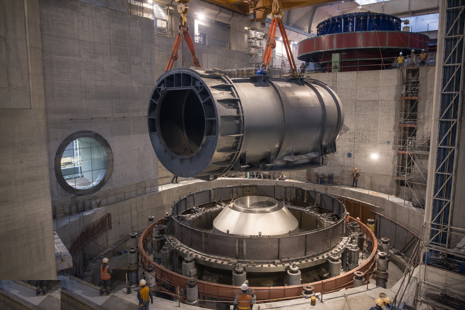
Install the water-passage steelwork from the bottom up: the draft-tube liner set plumb to datum, then the stay ring and spiral case assembled, aligned and welded out — with weld NDT and, where specified, a hydrostatic pressure test of the case before embedment. Survey everything in its final supported condition, because this steelwork is the machine's foundation. Anchor and brace it against the concrete to come.
Step 3: Monitor the embedment pours
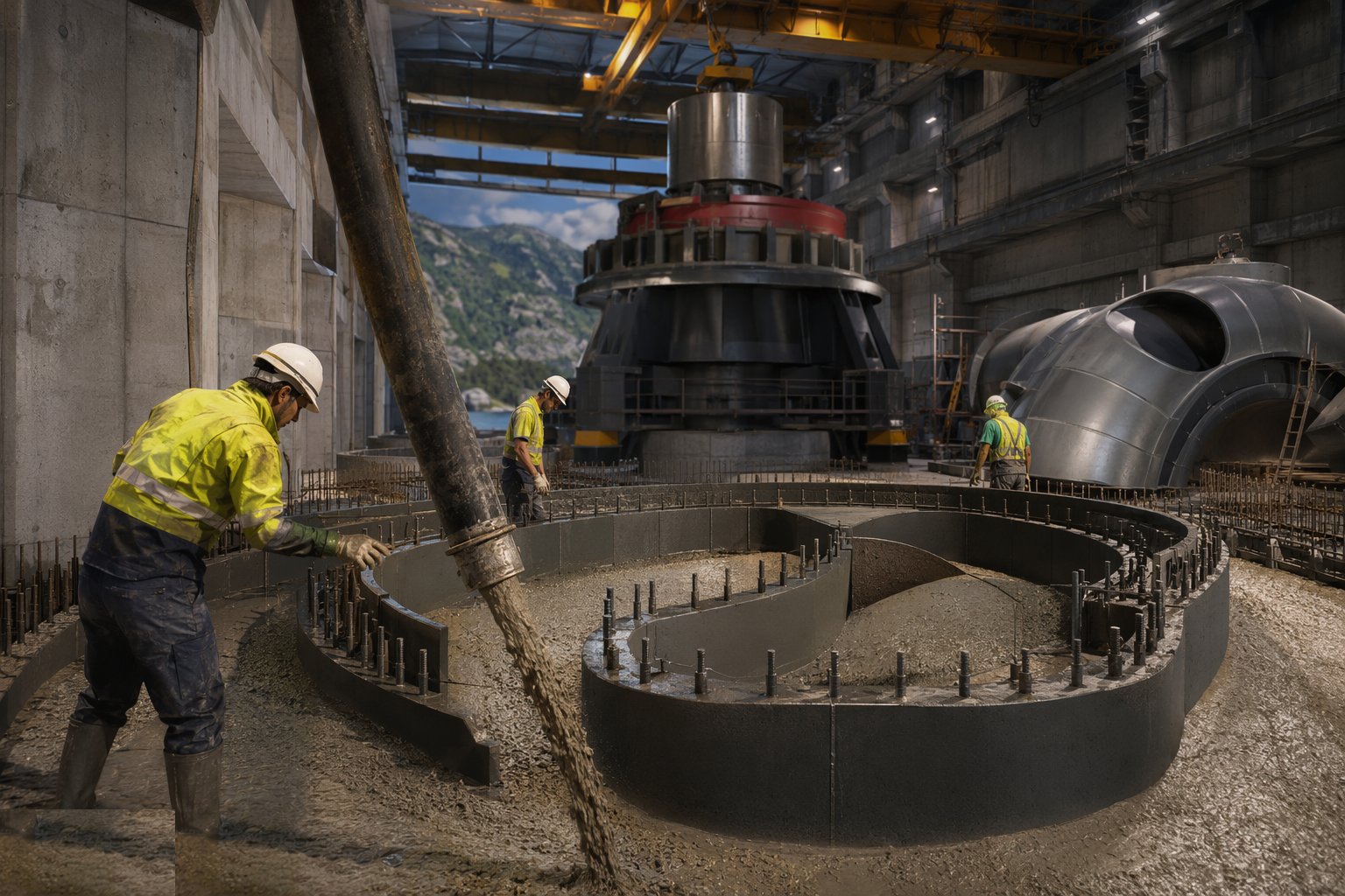
The civils cast the surrounding concrete in a controlled, symmetrical sequence while instruments and survey targets watch the case for movement. Pour rates, lift sequences and temperature are managed to the embedment procedure, and any detected distortion stops the pour for engineering review. This is the single most consequential civils-mechanical interface on the job — the records of it are kept for the life of the station.
Step 4: Assemble the turbine
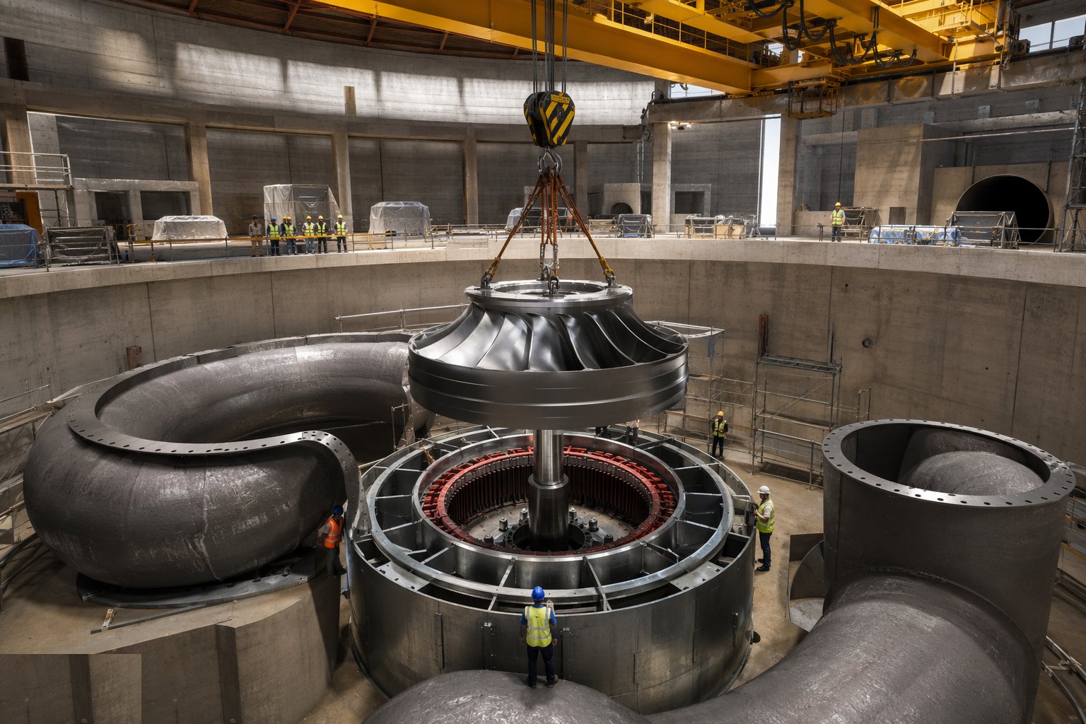
With the case embedded and cured, assemble the machine: wicket gates and their operating mechanism, the head cover, bearings and seals, then the runner and shaft lowered in and aligned to the generator axis. Set clearances and verify the alignment optically or by wire and micrometer — the shaft line is the reference for everything above it. Governor linkages are connected and stroked to prove full travel before oil is ever pressurised.
Step 5: Assemble the generator
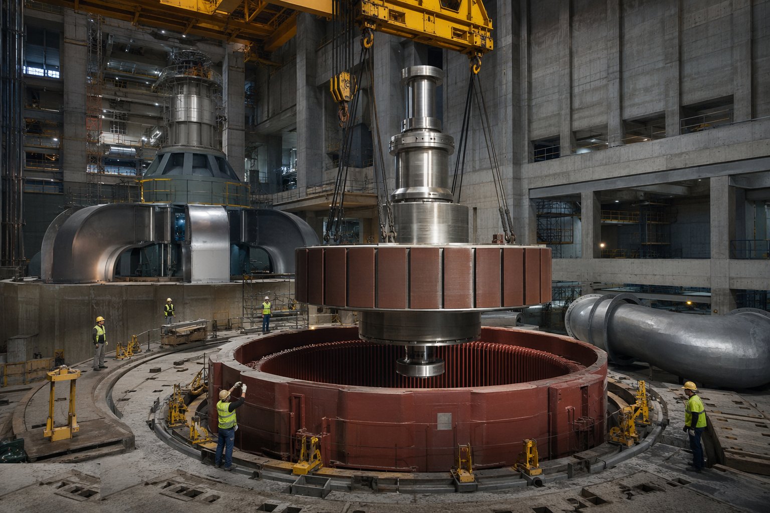
Stack the stator core and complete windings in situ where the machine is too large to ship assembled; build up the rotor — spider, rim and pole pieces — and lift it onto the shaft line. Set the air gap between rotor and stator to specification and record it around the full circumference; install the thrust and guide bearings, brakes and jacking systems. Dry electrical tests — insulation resistance, winding checks — are completed before any rotation is contemplated.
Step 6: Install the governor, hydraulic and auxiliary systems
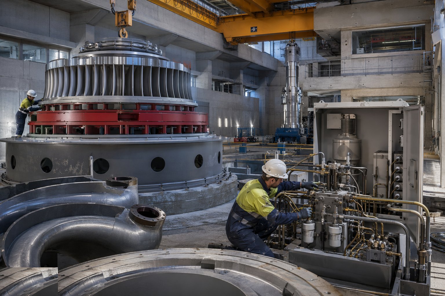
Install and flush the hydraulic power unit and its pipework to the cleanliness standard the servo valves demand — hydraulic cleanliness is the governor's lifeblood. Commission the cooling water, lubrication, compressed air, fire protection and drainage systems. Stroke the wicket gates under oil pressure against the governor, verify the control logic against the protection schedule, and test every trip and interlock dry.
Step 7: Build the switchyard and prove it dry
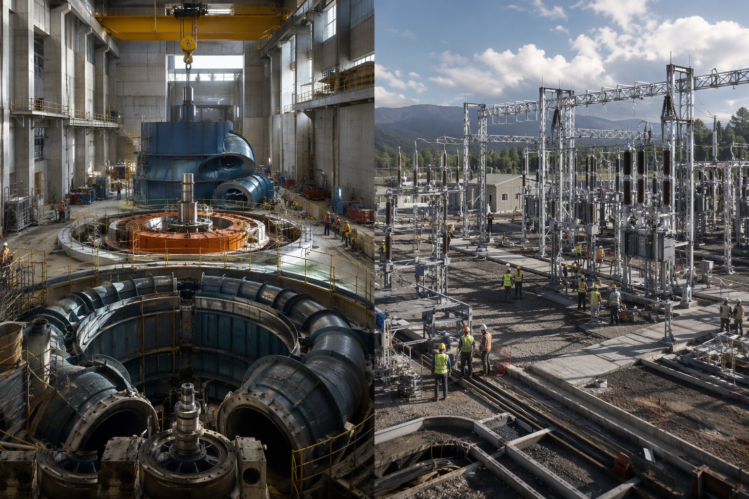
Install the generator transformers, switchgear — gas-insulated where space or environment dictates — protection panels, station services and SCADA. Terminate and test the cables, inject and prove every protection function, and complete the phasing and synchronising checks. The electromechanical phase closes with a dry-run regime: rotation checks on turning gear, simulated sequences and trip tests, all signed off — the next time the systems move for real, there will be water behind them.
Plant and equipment
- Powerhouse overhead travelling crane — installed and certified first
- Precision survey instruments — optical levels, total stations, piano wire and micrometers
- Welding sets and NDT equipment for case and penstock steelwork
- Hydraulic flushing rigs and particle-counting equipment
- Torque and tensioning equipment for machine bolts and couplings
- Insulation and winding test sets for the generator
- Protection injection and secondary test equipment for the switchyard
- Grouting and shimming equipment for sole plates and machine foundations
Quality control checks
- Dimensional handover survey of datums and embedments signed by civils and mechanical teams
- Weld maps and NDT records for liners, spiral cases and penstocks
- Spiral case pressure test and embedment-movement monitoring records retained
- Shaft alignment and bearing clearance records to supplier tolerances
- Generator air gap measured and recorded around the full circumference
- Hydraulic system cleanliness certified to the specified particle count
- Every protection trip and interlock proven dry and signed off
- Torque and tension records for all machine-critical connections
Safety considerations
- Heavy lifts by the powerhouse crane under lift plans — the highest-value suspended loads on site
- Confined spaces in spiral cases, draft tubes and pits — permits, ventilation, attendants and rescue
- Welding fume and grinding hazards in enclosed steelwork
- Hydraulic oil systems — injection injuries, fire risk and stored pressure
- Stored mechanical energy — brakes, springs and unbalanced rotors during assembly
- Electrical hazards as the switchyard nears energisation — permits and authorised persons
- Working at height inside the machine hall and over open pits — covers and edge protection maintained
Common defects
- Spiral case distorted during embedment — vibration and clearance problems for the machine's life
- Datums lost or mixed between civils and mechanical teams — assemblies that will not align
- Hydraulic pipework flushed inadequately — servo valves failing in the first year
- Air gap out of tolerance discovered at first rotation — the rotor comes out again
- Weld defects in cases or penstocks found at pressure test — cut out and re-welded on the critical path
- Protections untested dry — first real trip reveals a wiring error under load
- Crane certified late — the whole installation sequence slipping behind it
- Interface records incomplete — commissioning and warranty arguments without evidence
Best suited for
- Turbines and generators set to machining tolerances
- Governors, switchgear and the switchyard connection
- Heavy lifts threaded into a finished concrete shell
- The transition from civil engineering site to power station
How long does Electromechanical Installation take?
Typical duration: Electromechanical installation in a two-to-four-unit powerhouse commonly runs 12–24 months end to end, heavily overlapped with the civils; assembly of each machine is measured in months, and the switchyard and dry-testing phase adds a further season before water..
Related processes
- Wind Farm Electrical Infrastructure
- Commissioning & Energisation
- River Diversion & Cofferdams
- Dam & Powerhouse Civils
- Impoundment, Commissioning & Handover
- Ground-Source Heat Pumps — Homes & Villas
- Shallow Geothermal — Commercial & District Schemes
- Deep Geothermal Drilling & Wells
- Geothermal Plant, Connection & Commissioning
- Site Access & Enabling Works
- Survey, Ground Investigation & Resource Studies
- Piling & Mounting Structures
- PV Module Installation
- Electrical Balance of System
- Grid Connection & Energisation
- Wind Turbine Foundations
- Craneage & Tower Erection
- Power Generation sector guide
- Utilities & Energy group