Wind Farm Electrical Infrastructure
Kilometres of buried 33 kV array cable stitched from turbine to turbine, a collector substation, and the grid compliance work that turns a field of machines into a power station.
Last updated 2026-07-28 by the BuildPedia Editorial Team.
What is Wind Farm Electrical Infrastructure?
A wind farm's electrical system starts inside each turbine, where a transformer — in the tower base or the nacelle — steps the generator output up to the collection voltage, commonly 33 kV for onshore schemes. From there, array cables run in strings from turbine to turbine, buried alongside the access tracks, until each string lands back at the collector substation. The substation holds the switchgear, the main transformer stepping up to export voltage, the metering and protection, and the point where the developer's asset ends and the network operator's system begins. It is an entire electrical distribution network built across farmland or moor, most of it invisible once the topsoil goes back.
Most of the physical work is cable installation: trenching, bedding, laying, jointing and backfilling, repeated for kilometre after kilometre. The detail that protects the investment is boring and absolute — correct bedding sand, correct depth, warning tape above, ducts where future pulling may be needed, and fibre laid with the power cables for the SCADA system. Where the route meets an obstacle that cannot be open-cut — a river, a railway, a trunk road — the crossing goes in by horizontal directional drilling (HDD), a steered bore that pulls duct or cable through without breaking the surface. Joint bays, where cable drums meet, are left as open works until certified jointers have made the joints and the records are complete.
The substation and the grid connection are where the paperwork becomes physical. In the UK, distribution-connected schemes work through the DNO under the ENA G99 engineering recommendation regime, while larger transmission-connected schemes answer to the Grid Code administered by NESO — either way there are protection settings, fault-level studies and compliance witness tests that must be agreed before energisation. Offshore, the same architecture scales up: armoured inter-array subsea cables — traditionally 33 kV, with 66 kV common on newer schemes — feeding an offshore substation and a high-voltage export cable to shore. In the Gulf, wind schemes are few, but any grid connection runs through the utility's own process — DEWA in Dubai, EWEC and TRANSCO in Abu Dhabi — and cable routes through desert ground need the same NOC-based service clearances as any other utility work.
When and why is Wind Farm Electrical Infrastructure used?
Cable installation follows the tracks and foundations and runs in parallel with erection — the trenches use the same access, and each string is typically ready before its turbines are. The substation sits on the critical path regardless, because nothing can be energised, let alone commissioned, until the substation is complete and the network operator has accepted the protection and compliance arrangements. The stage matters commercially as well as technically: a buried cable fault found after energisation is among the most expensive defects in the sector to locate and repair, and a grid compliance failure found late can hold a finished wind farm off the system while its warranties and revenue clock run. A single small turbine skips this entire world: its output lands at a consumer unit through a dedicated circuit, with the network operator notified under ENA G98 rather than contracted under G99 — no 33 kV, no substation, but the same insistence on certified joints, tested protection and permission before energisation.
Types of Wind Farm Electrical Infrastructure
Trenched array cable network
Direct-buried or ducted MV cables laid in open trenches along the access-track corridors, on sand bedding with warning tape above and fibre for SCADA in the same run. The default onshore method — fast, cheap per metre, and entirely dependent on bedding, depth and backfill discipline.
Horizontal directional drilling crossings
Steered bores drilled beneath rivers, railways, canals and highways, pulling duct or cable through without open-cut. Slower and far more expensive per metre than trenching, and requiring specialist crews, but often the only permitted way across a protected crossing.
Offshore inter-array and export cables
Armoured submarine cables laid and buried in the seabed — inter-array strings collecting to an offshore substation, then a high-voltage export cable to landfall. Installed by specialist cable-lay vessels with burial tools, within marine weather windows and consent conditions.
Collector substation
The fenced compound holding MV switchgear, the main transformer on its bunded bay, metering, protection panels and SCADA. Outdoor air-insulated layouts dominate on land; gas-insulated switchgear shrinks the footprint where space or environment demands it.
Wind Farm Electrical Infrastructure: step by step
Step 1: Clear and prove the cable route
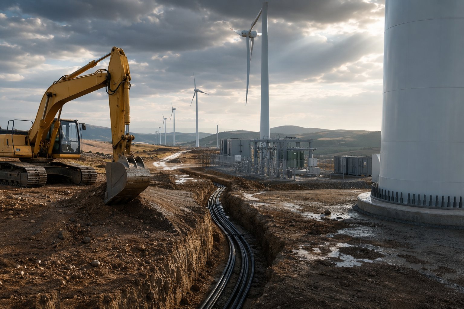
Walk and survey the whole route before a bucket touches it: utility records, CAT scans and ground radar, trial holes at every conflict point, and the wayleaves and landowner agreements confirmed. Set out the trench line, joint bay positions and HDD entry and exit pits, and agree crossing consents with river, rail and highway authorities — the consents calendar, not the digging rate, usually sets the programme here.
Step 2: Excavate trenches and form the crossings
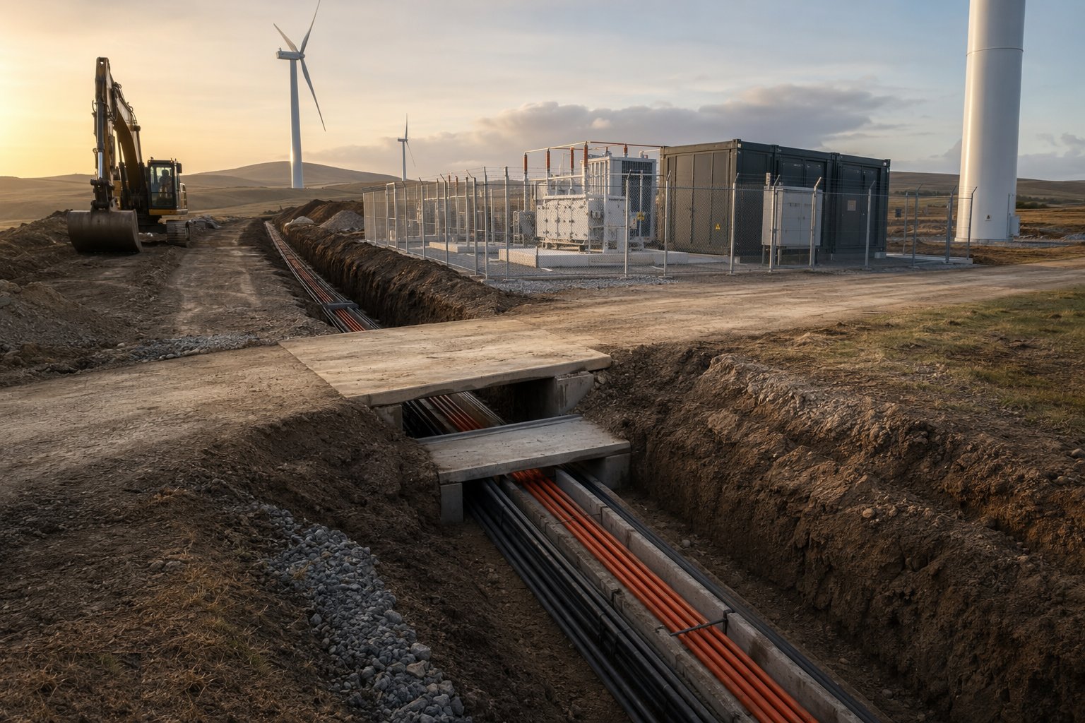
Open the trenches to the specified depth and width, supporting or battering as the ground demands and managing water as it comes. At protected crossings, the HDD crew drills the steered pilot bore, reams it out and pulls the duct through — with drilling-fluid control and breakout monitoring as consent conditions, especially under rivers and railways. Prove every duct with a mandrel before cable is ordered to it.
Step 3: Lay bedding, ducts and cable
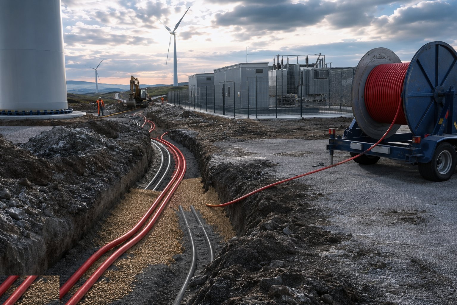
Place the specified bedding sand, lay ducts or direct-buried cable from drum trailers and cable handling equipment, and keep bending radii and pulling tensions within the cable manufacturer's limits — both are recorded. Lay the fibre in its own duct in the same run, reinstate with warning tape at the specified depth above, and backfill in layers that will not drop stones onto the cable. Joint bays stay open and protected until the jointers are done.
Step 4: Joint and terminate the cables
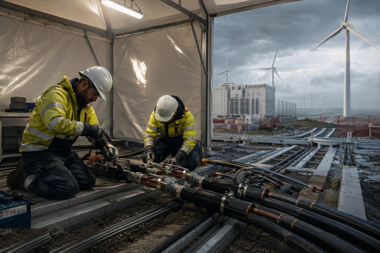
MV joints and terminations are made by certified jointers under controlled conditions — cleanliness, moisture control and the jointer's own records for every joint, because a joint is the statistically weakest point in any buried network. Terminate at the ring main units or switchgear in the substation and at each turbine transformer, and label and record every end so the as-built network diagram matches the ground truth.
Step 5: Build the substation
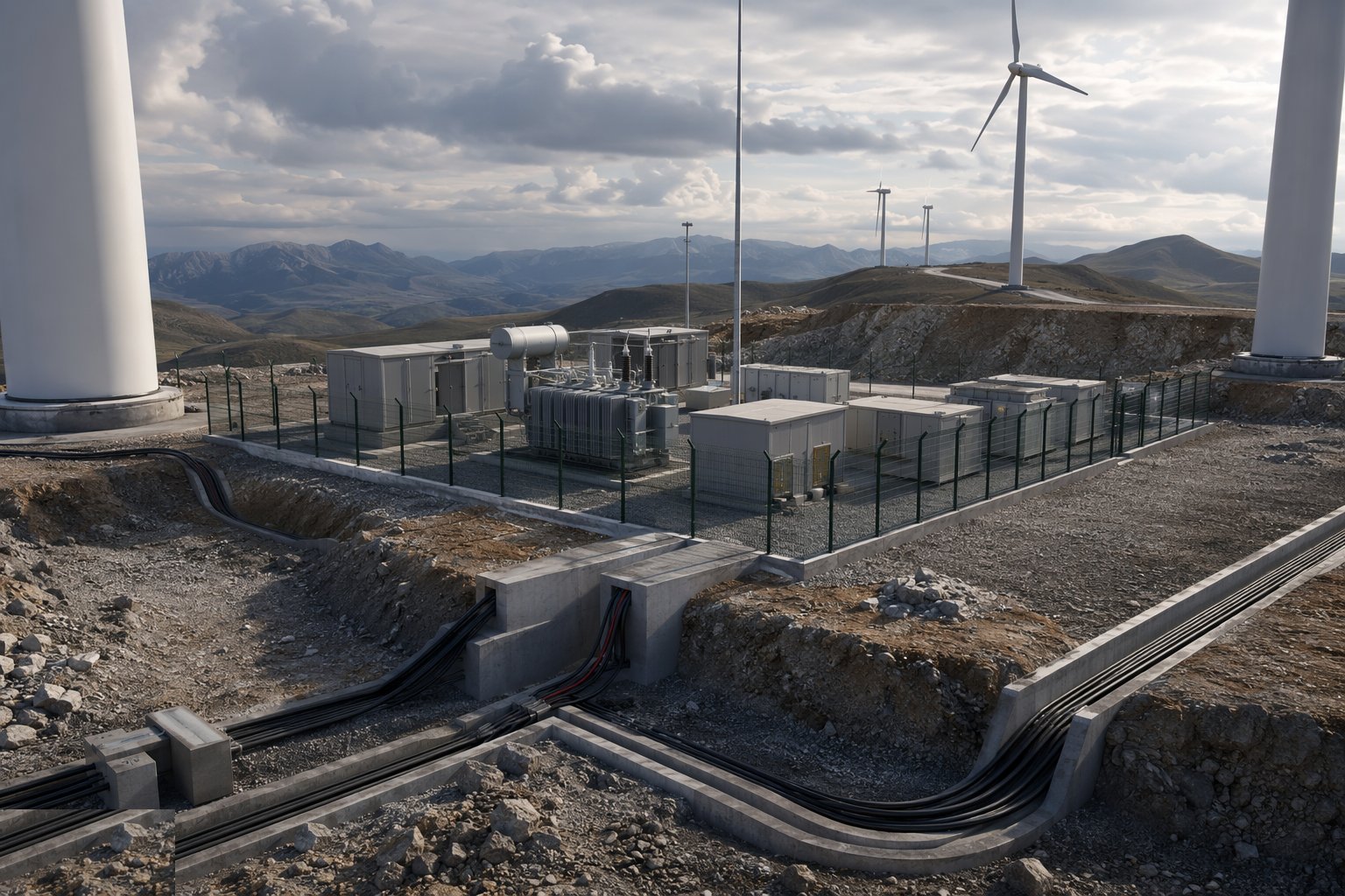
The substation civils go first — foundations, the bunded transformer bay, cable basements or trenches, drainage and the building or housings — then the plant: MV switchgear, the main transformer delivered as an abnormal load and positioned on its bay, protection and control panels, batteries and chargers, and the SCADA integration back to the control room. Oil containment to the bunded bay and fire protection are inspected before energisation is even discussed.
Step 6: Earth, protect and test the network
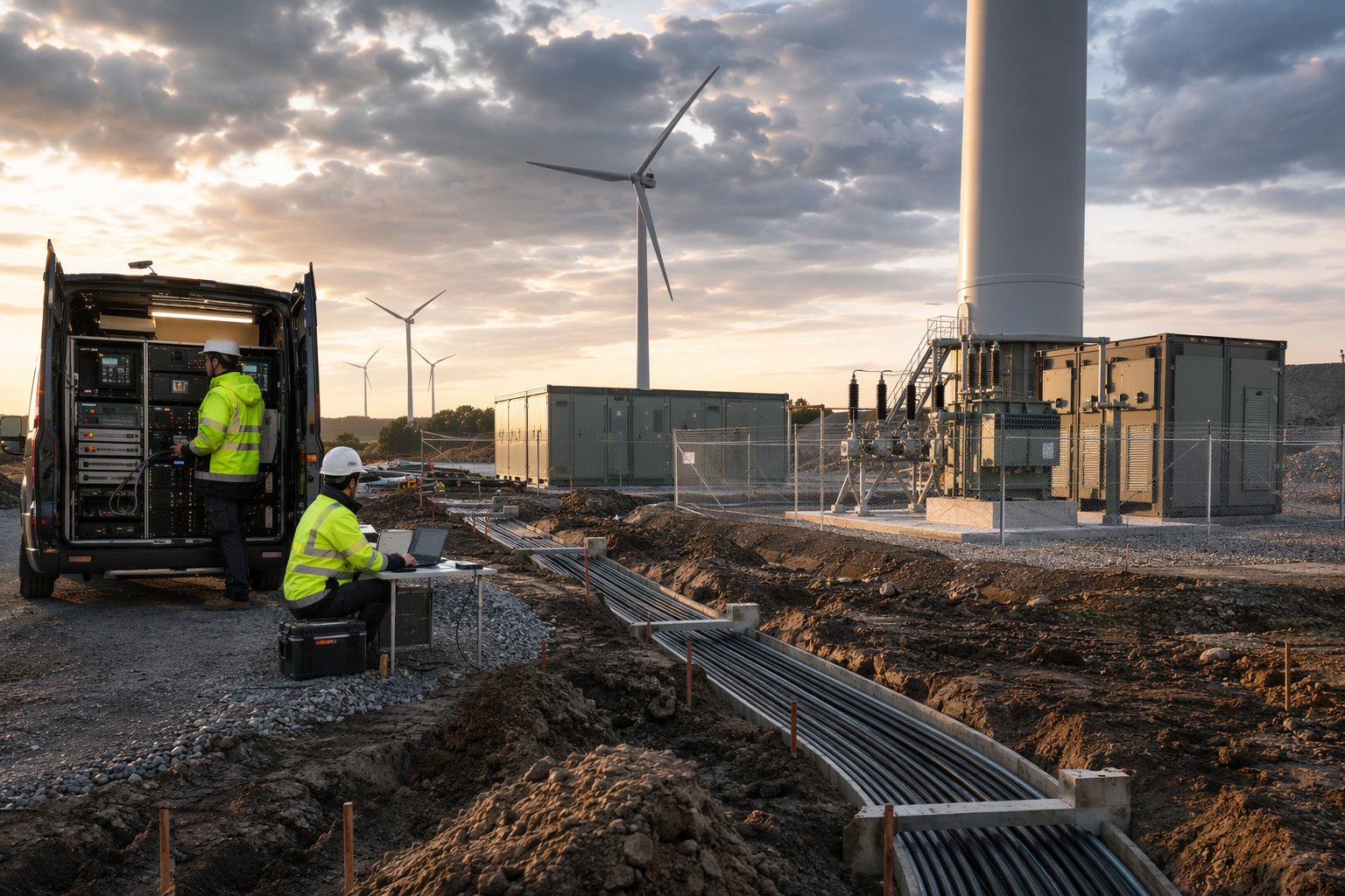
Install and test the earthing — the substation earth grid, turbine earths and their interconnection — and measure the results. Test the installed cables: sheath integrity, phasing and, for MV systems, a withstand test — VLF testing is common practice — with results recorded per section. Inject and prove every protection function: the settings agreed with the network operator are the settings in the relays, witnessed and signed.
Step 7: Pre-commission with the network operator
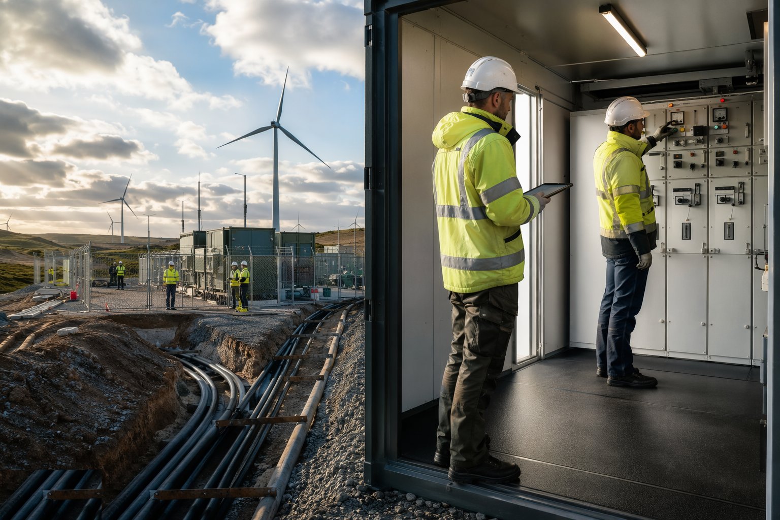
Before any energisation, complete the operator's process: the compliance evidence under G99 or the Grid Code, protection witness tests, SCADA point-to-point checks, and the agreed switching schedule with named authorised persons on both sides. Only when the operator accepts the installation is an energisation date fixed — and that date is the gateway to the entire commissioning programme that follows.
Plant and equipment
- Trenching excavators, rock saws and vacuum excavators
- Cable drum trailers, pulling winches and tension-monitoring equipment
- HDD rigs with drilling-fluid recycling plant
- Certified MV jointing teams with controlled-environment jointing shelters
- Mobile cranes and abnormal-load transport for the main transformer
- VLF test sets, sheath testers and protection injection test equipment
- Earth grid installation and earth-testing instruments
- Fibre blowing and splicing equipment
Quality control checks
- Route clearance records — scans, trial holes and wayleaves — filed before excavation
- Bedding, depth, warning tape and backfill checked per section before covering
- Cable pulling tensions and bending radii recorded against manufacturer limits
- Every joint and termination recorded with the certified jointer's documentation
- Cable test results (sheath, phasing, withstand) filed per section before energisation
- Protection settings witnessed and matched to the network operator's agreed schedule
- As-built network records and drawings reconciled to the installed route
Safety considerations
- Permit-to-dig discipline with service clearance at every excavation — HSG47 practice
- Trench support, battering and edge protection; no entry into unsupported excavations
- Cable pulling hazards — stored energy in tensioned ropes, crush points at drums and rollers
- HDD drilling-fluid management and inadvertent return (breakout) response under consents
- Working adjacent to live network-operator apparatus at the point of connection
- HV competence — only authorised persons switch or test on the MV network
- Oil-filled plant: bund integrity and fire precautions before first filling and energisation
Common defects
- Cable damaged at installation — kinked, over-pulled or struck during backfill — failing in service
- Bedding omitted or contaminated, leaving the cable on stones
- Joints made in poor conditions — moisture or contamination tracked into the joint
- Warning tape or ducts omitted — the next excavator finds the cable with a bucket
- Joint bays backfilled before test results are received
- Protection settings left at defaults instead of the network operator's agreed values
- Fibre route broken or mislabelled — SCADA blind to part of the array
- As-built records drifting from reality, crippling later fault location
Best suited for
- Kilometres of buried array cable stitched between turbines
- The collector substation and grid-compliance works
- Trenching, jointing and termination across open country
- Turning a field of machines into a single power station
How long does Wind Farm Electrical Infrastructure take?
Typical duration: Cable gangs commonly install several hundred metres per day each in open ground, so onshore array cabling runs for 3–9 months across a scheme with several gangs; the substation build typically takes 6–12 months and sits on the critical path to energisation; HDD crossings are programmed individually against consents..
Related processes
- Electrical Balance of System
- Grid Connection & Energisation
- Wind Turbine Foundations
- Craneage & Tower Erection
- Commissioning & Energisation
- River Diversion & Cofferdams
- Dam & Powerhouse Civils
- Electromechanical Installation
- Impoundment, Commissioning & Handover
- Ground-Source Heat Pumps — Homes & Villas
- Shallow Geothermal — Commercial & District Schemes
- Deep Geothermal Drilling & Wells
- Site Access & Enabling Works
- Survey, Ground Investigation & Resource Studies
- Piling & Mounting Structures
- PV Module Installation
- Geothermal Plant, Connection & Commissioning
- Power Generation sector guide
- Utilities & Energy group