Craneage & Tower Erection
The heaviest lifts most construction professionals will ever see — a main crane the size of a small building, tower sections, a nacelle and blades as long as a football pitch, all governed by certified crane pads and wind limits.
Last updated 2026-07-28 by the BuildPedia Editorial Team.
What is Craneage & Tower Erection?
Erection is the stage everyone pictures: the tower sections stacked one on another, the nacelle landed on top, and the blades lifted to the hub. Each of those components arrives as an abnormal load — blades and tower sections on extendable trailers under escort — and each lift is executed by a main crane chosen for the worst case it will face: usually the nacelle, the heaviest single component, lifted to full hub height. An assist crane tails loads off the ground and handles the smaller lifts. Everything hangs off the crane pad: a purpose-built stone platform beside each foundation, designed for the actual crane loads, inspected and certified before the crane tracks or outriggers go onto it.
The main crane decision is between a lattice-boom crawler crane — the traditional choice for large onshore machines, assembled on site and tracked slowly from pad to pad — and a large all-terrain mobile crane, which mobilises and derigs fast and suits smaller turbines or tight programmes. Either way, the governing constraint is rarely the machine's paper capacity; it is the wind. Turbine components are enormous sails, and every lift carries a manufacturer's wind-speed limit that tightens as the component's area grows — blades are the tightest of all. A wind farm erection programme is therefore written in weather windows, not calendar dates.
The industry runs on its own safety culture: the Global Wind Organisation (GWO), founded by the major turbine manufacturers and operators, whose Basic Safety Training — working at heights, first aid, manual handling and fire awareness, plus sea survival for offshore work — is the standard passport for anyone working in or on a turbine. Offshore erection is the same logic executed from purpose-built jack-up installation vessels, with marine weather windows and vessel motions replacing the crane pad as the governing constraint. In the Gulf, where wind schemes are rare, the same international lifting and GWO discipline is imported wholesale with the contractor and the turbine supplier.
When and why is Craneage & Tower Erection used?
Erection follows the foundations — each base must be cured to full strength, backfilled and certified, and its crane pad completed and certified, before the main crane arrives — and it must finish ahead of electrical termination and commissioning, because a turbine cannot be energised until it is mechanically complete. It matters because it concentrates the project's highest-value assets and its highest-risk operations into the same few weeks: one dropped component or one crane incident can write off a machine and a season, and the erection rate, paced by weather windows, is what ultimately decides when the first megawatt is exported.
Types of Craneage & Tower Erection
Lattice-boom crawler crane
The traditional main crane for large onshore turbines: enormous capacity at long radii and great heights, assembled on the pad from dozens of wagon loads and tracked slowly between positions. Suits big machines and rolling sites, at the cost of long rigging and derigging time at each end of the job.
Large all-terrain mobile crane
A road-mobile telescopic crane in the largest classes, sometimes with luffing jib or superlift attachments. Mobilises, rigs and derigs in days rather than weeks, making it economic for smaller turbines, tight programmes or sites where the crawler's slow pad-to-pad travel is a liability — with capacity limits that rule it out as turbines grow.
Single-blade versus pre-assembled rotor installation
Blades can be lifted individually to a hub already on the tower — lower crane demand and smaller pads, but more lifts and more time at height — or assembled with the hub at ground level into a complete rotor lifted as one, which is faster aloft but needs the largest crane capacity and pad area. Larger machines increasingly force the single-blade route, using dedicated blade clamps and lifters.
Offshore installation vessels
Purpose-built jack-up wind turbine installation vessels that stand on the seabed and lift components from their own decks, with floating crane vessels increasingly used for the largest machines. The lifting logic is the same as onshore; the constraints are vessel motions, marine weather windows and offshore logistics.
Small and building-mounted turbines
Sub-100 kW machines on farms, smallholdings and commercial buildings go up on tapered monopole towers — typically tilted up by winch or lifted by a single modest mobile crane in one or two picks, with no crawler crane and no certified-pad industry behind them. The lifting-plan discipline still applies in full: ground bearing, wind limits, exclusion zones and a competent person in charge, because a small rotor is still a sail and a tilt-up tower is still a suspended load. In the UK these connect under the G98 notification route rather than the G99 approval regime, and planning treatment differs from utility wind — check the local authority before the order is placed.
Craneage & Tower Erection: step by step
Step 1: Design and certify the hardstand and crane pad
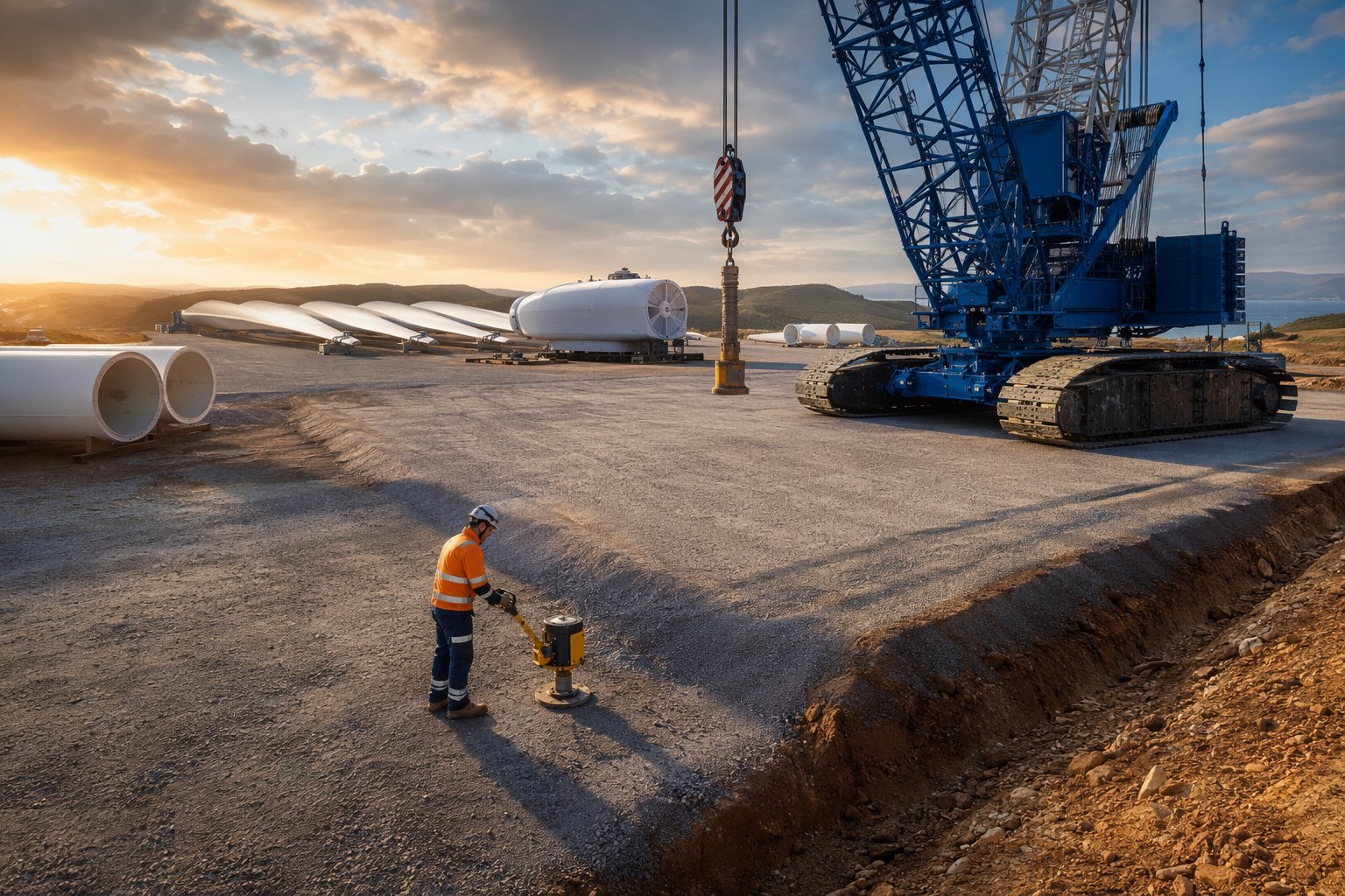
The crane pad is a designed structure, not a layer of hardcore: its bearing capacity comes from the ground investigation, and it is built up with geotextile separation and compacted stone to carry the crawler tracks or outrigger loads the crane supplier publishes. Inspect and test the formation, record the construction, and have the platform certified before the crane arrives — the same working-platform discipline that protects piling rigs applies here, because a crane that goes out of level under load is a fatal event. Size the pad for the assembly method chosen — a pre-assembled rotor lift needs room to lay out a rotor the size of a small roundabout.
Step 2: Plan the lifts and the abnormal-load logistics
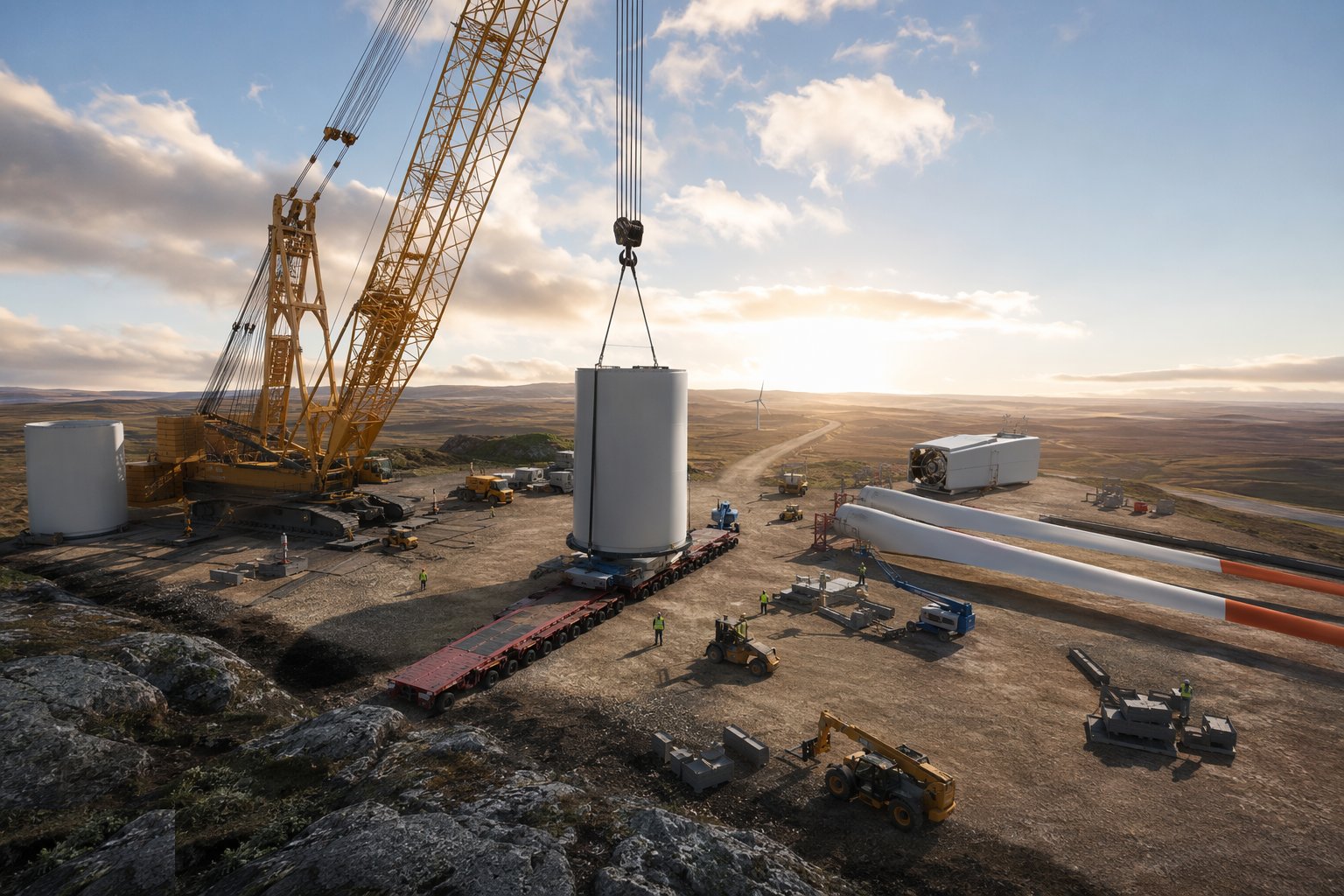
Every lift gets a lift plan prepared under an appointed person, with the crane configuration, radii, capacities, rigging and wind limits written down, and exclusion zones set. In parallel, run the transport: route surveys, swept-path analysis, escort arrangements and a delivery sequence that matches the erection order — a blade that arrives before its tower section blocks the site for a week. Brief the whole site from the same sequence, and agree the weather-decision protocol: who calls a lift off, against which forecast, and how far ahead.
Step 3: Erect the base tower section
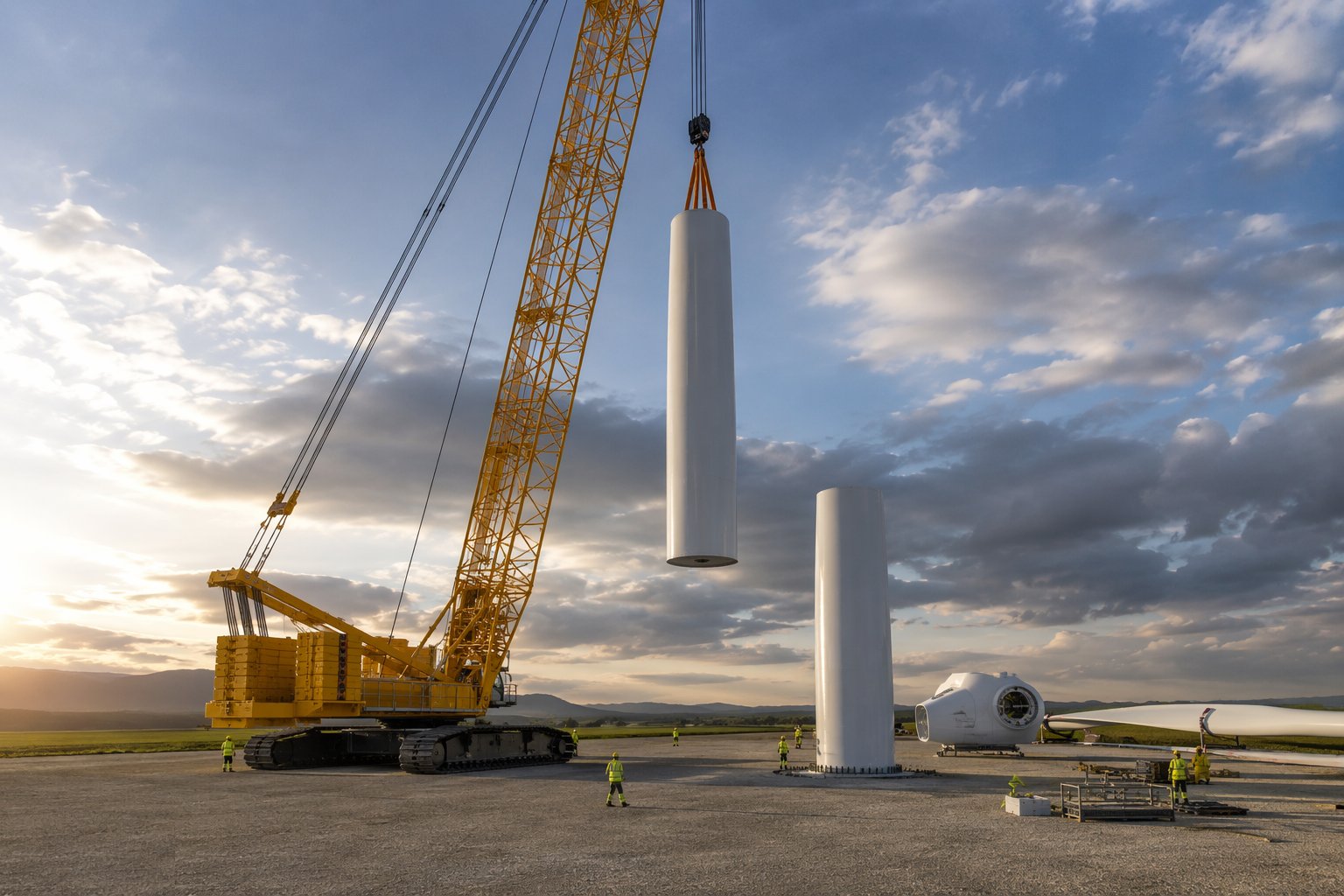
The bottom section lands on the anchor cage bolts — the moment of truth for the foundation survey. Level it, tension the foundation bolts to the specified values and sequence with calibrated hydraulic tools, and grout the interface beneath the base flange where the design calls for a grout joint, testing the grout cubes as it goes. Survey the section for verticality before releasing the crane; every error here multiplies up the tower.
Step 4: Stack the tower sections
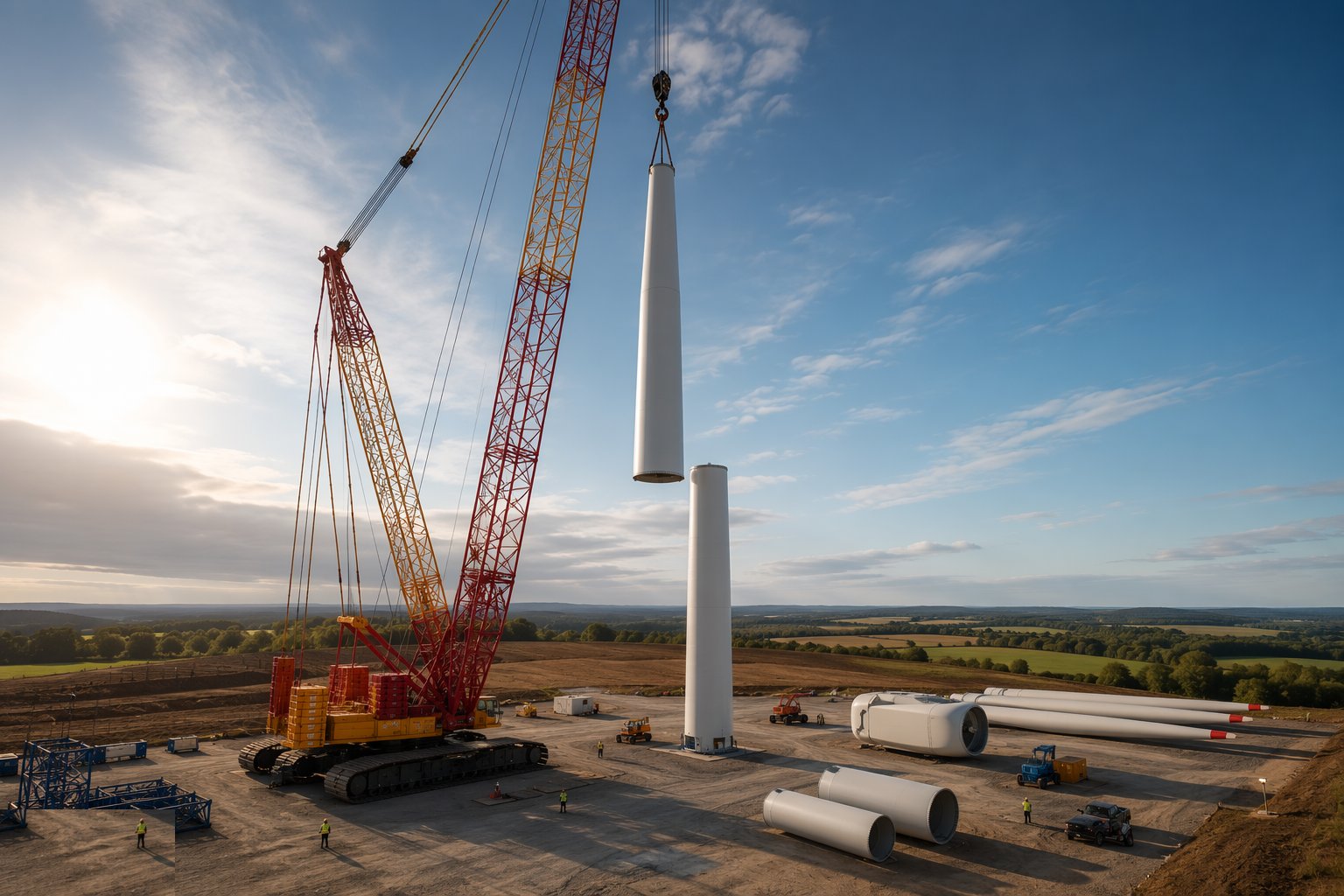
Mid and top sections follow, each landed, bolted and tensioned in sequence with torque and tension records kept for every bolt. Fit the internal cable ladders, platforms, lighting and fall-arrest systems as the tower grows — working at height under GWO discipline, with tools and components tethered against dropped objects. The assist crane tails sections off their transport frames; nobody stands under a suspended load, and wind limits are watched continuously.
Step 5: Lift the nacelle and hub
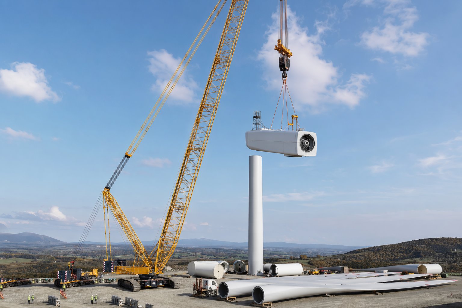
The nacelle is usually the heaviest single lift and the one the crane was selected for. Lift it in a confirmed weather window, control it with tag lines, land it on the top flange and bolt up to the specified tension. If the installation method is pre-assembled rotor, the hub and blades have already been built up at ground level and this is the largest lift of the project; if single-blade, the hub alone goes up with or behind the nacelle.
Step 6: Lift the blades
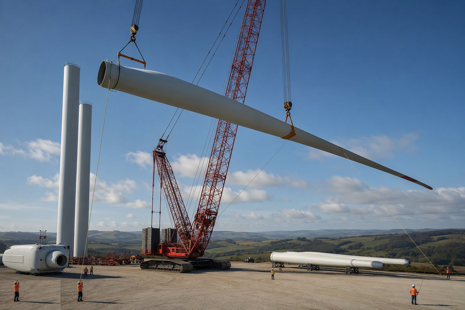
Blade lifts carry the tightest wind limits because a blade is pure sail area. Single blades are lifted with a dedicated blade clamp or yoke that grips the root and controls pitch orientation; a pre-assembled rotor is lifted by the hub with blades hanging — a spectacular lift that needs the calmest window of the job. Control with tag lines from the ground, land the blade root on the hub studs or the rotor on the main shaft flange, and bolt and tension to spec. Complete pitch and manual-rotation checks before releasing the crane.
Step 7: Mechanical completion and handover
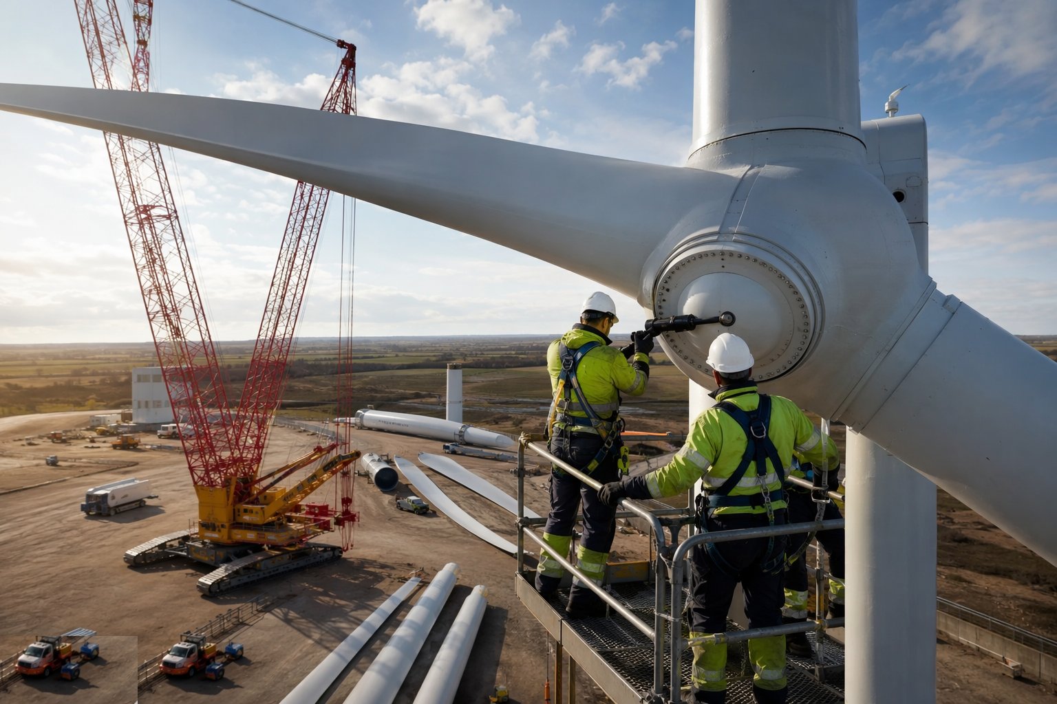
Close out every record: bolt torque and tension records for the whole machine, grout test results, the verticality survey, component receipt and damage inspections, and the snag list walked down and cleared. The completed turbine is handed to the electrical and commissioning team with a mechanical completion certificate — from here, no one works in or on the machine without the commissioning permit regime, because the next time the systems move, they move under power.
Plant and equipment
- Main crane — lattice-boom crawler or large all-terrain mobile crane
- Assist crane for tailing and secondary lifts
- Blade clamps, yokes and lifters, and rotor assembly frames
- Calibrated hydraulic torque and bolt-tensioning tools
- Component transport frames, extendable trailers and escort vehicles
- Tag lines, rigging tackle and certified lifting accessories
- MEWPs and tower access equipment for external work
- Site anemometry and weather-monitoring equipment at crane height
Quality control checks
- Crane pad and hardstand formation tested, constructed to design and certified before crane assembly
- Lift plans prepared and signed off under an appointed person for every lift
- Bolt torque and tension records for every connection, with calibrated tool certificates
- Grout cubes tested for base-flange grout joints
- Tower verticality surveyed at completion and compared to tolerance
- Component receipt and damage inspections recorded before lifts
- Wind speeds logged through every lift against the manufacturer's limits
Safety considerations
- LOLER-compliant lifting operations: appointed person, lift plans, exclusion zones under suspended loads
- Dropped-object prevention — tethered tools and components at height, hard barriers below
- Crane stability on certified pads — outrigger or track bearing verified, level monitored
- Working at height under GWO discipline, with rescue-from-height provision at all times
- Wind limits enforced with real-time anemometry and a defined authority to stop lifts
- Abnormal-load movements on public roads — escorts, timing restrictions and route discipline
- Fatigue and journey management for crews on remote sites in short weather windows
Common defects
- Crane pad settled or overstressed — crane out of level and the site stopped mid-programme
- Bolts tensioned to the wrong value or out of sequence — flange joints that must be re-worked at height
- Grout voids or low grout strength beneath the base flange
- Blade leading edges or lightning receptors damaged in handling or transport
- Tower flange faces damaged on landing — expensive remediation before stacking continues
- Delivery sequence wrong — components double-handled or the crane stood idle waiting
- Weather-window discipline broken — a lift started in marginal conditions and abandoned with a load in the air
Best suited for
- The heaviest lifts most construction professionals will ever see
- Certified crane pads and strict wind-speed limits governing every lift
- Tower sections, nacelles and blades assembled aloft
- Programmes ruled entirely by weather windows
How long does Craneage & Tower Erection take?
Typical duration: Commonly 2–5 clear-weather days to erect a large onshore machine once the cranes are rigged on the pad; a well-run site averages roughly a turbine a week across a season, with crawler crane rigging and pad-to-pad moves and wind downtime built into the programme..
Related processes
- PV Module Installation
- Electrical Balance of System
- Grid Connection & Energisation
- Wind Turbine Foundations
- Wind Farm Electrical Infrastructure
- Commissioning & Energisation
- River Diversion & Cofferdams
- Dam & Powerhouse Civils
- Electromechanical Installation
- Impoundment, Commissioning & Handover
- Ground-Source Heat Pumps — Homes & Villas
- Shallow Geothermal — Commercial & District Schemes
- Site Access & Enabling Works
- Survey, Ground Investigation & Resource Studies
- Piling & Mounting Structures
- Deep Geothermal Drilling & Wells
- Geothermal Plant, Connection & Commissioning
- Power Generation sector guide
- Utilities & Energy group