Electrical Balance of System
Strings to inverters, inverters to the substation, and the SCADA that watches it all — the trenches, cables, MV skids and switchgear that turn thousands of modules into a power station.
Last updated 2026-07-28 by the BuildPedia Editorial Team.
What is Electrical Balance of System?
Balance of system is everything electrical between the module terminals and the grid connection point, and on a solar farm it is the stage where the site stops looking like a field of tables and starts behaving like a power station. The DC side gathers the strings into inverters. Two architectures dominate: string inverters — wall- or rack-mounted units of typically 100 to 350 kW scattered through the field, each converting a handful of strings — and central inverters — multi-megawatt containerised stations on concrete pads, fed through DC combiner boxes. String architecture gives finer maximum-power-point tracking and simpler replacement; central architecture concentrates conversion into maintainable, weather-protected stations and is common on the largest desert plants. Either way, the inverter output is low-voltage AC, stepped up to medium voltage — commonly 11 or 33 kV — by transformers at the inverter stations or on MV skids, and collected by buried MV cable rings into the site substation.
The cabling is civil engineering as much as electrical. DC home runs route on the structures; MV and AC collector cables bury in trenches across the whole site — excavated, sand-bedded, laid with separation from other services, covered with warning tape and backfilled in compacted layers, with ducts at road crossings and under future drainage routes. Thermal matters more than newcomers expect: cable ratings depend on the ground's ability to conduct heat away, and dry desert sand is a poor conductor, so Gulf collector designs derate cables for soil thermal resistivity and ambient temperature — a cable sized from a catalogue rating table without the site's thermal survey is a cable that runs hot for thirty years. Joints and terminations on the MV network are made by qualified jointers with recorded procedures, and every cable is identified, tested and mapped before backfill.
The substation and the SCADA close the stage. The substation — MV switchroom, main transformer stepping up to the export voltage, protection, metering and the grid interface — is usually a design-and-build package with its own civils, and its protection settings must match the connection agreement exactly, because the DNO or transmission operator will witness the proving tests. The SCADA and communications network — fibre rings through the field, inverter and tracker interfaces, meteorological stations, CCTV and perimeter detection — is installed alongside and commissioned point by point, because a solar farm is operated from a screen: availability, string currents, tracker positions and alarms all surface there first. In the UK the contestable connection works may be built by an independent connection provider under DNO adoption rules; in the UAE, utility-scale plants interface with TRANSCO in Abu Dhabi or DEWA's network in Dubai under the project's connection conditions.
When and why is Electrical Balance of System used?
Balance of system runs behind module installation — strings can only be tested and connected once they exist — and alongside the substation package, because everything converges at the point of connection. It matters because it is where generation becomes exportable: an incomplete collector network or an unproven protection relay is the difference between a finished field and a revenue-earning plant. It matters technically because buried electrical work is unforgiving — a damaged MV joint, a thermally underrated cable or a swapped fibre core is buried under a working site and found at energisation or in service — and it matters contractually because the grid-witness tests at the end of this stage are gated by the connection agreement, the document the whole project's revenue date hangs from. At villa scale the balance of system collapses to an inverter beside the consumer unit, DC isolators, a generation meter and a few metres of cable — but the DC run still wants its clips, its segregation and its polarity test, and the inverter still earns its place on the utility's approved-equipment list before anyone switches it on.
Types of Electrical Balance of System
String inverter architecture
Field-distributed inverters of typically 100–350 kW mounted on racks or posts through the array, each converting a few strings to low-voltage AC, aggregated at local transformers. Fine-grained MPPT, no single large point of failure, and unit swap-out as the maintenance model — but thousands of devices to install, configure and address on the SCADA.
Central inverter and MV skid architecture
Containerised multi-MW inverter stations on concrete pads, fed by DC combiner boxes, with integrated or adjacent step-up transformers on MV skids. Fewer, larger units in maintainable enclosures — common on the biggest desert plants — with heavier civils and lifting, and a single outage costing more output, managed through redundancy.
Collector network and trenching
The buried MV and AC cable rings, ducts and trenches linking inverter stations to the substation, plus DC home runs on the structures. Sand bedding, separation, warning tape, thermal design to the site's soil survey, qualified jointing and full test-and-map records before backfill — the invisible half of the plant's electrical value.
Substation, SCADA and communications
The grid-interface package: MV switchgear, main transformer, protection and metering to the connection agreement, plus the fibre rings, inverter and tracker interfaces, met stations and CCTV that make the farm operable from a control screen. Usually a specialist package with its own civils, FAT/SAT regime and grid-witnessed tests.
Electrical Balance of System: step by step
Step 1: Set out and excavate the cable network
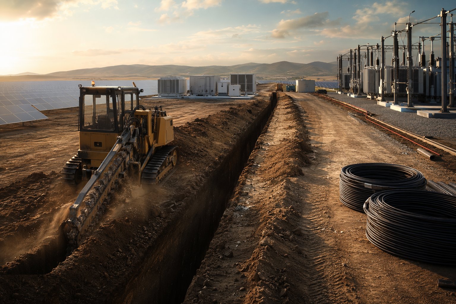
Set out the trench and duct routes from the collector design, clearing services and archaeology as you go, and excavate with the bedding, separation and depth the design specifies. Install ducts at crossings and future routes before they are needed — retrofitting a duct under a live haul road or a completed drainage swale is a lesson learned once. In the Gulf, confirm the soil thermal resistivity survey is current and the cable schedule derates for it before a single drum is ordered.
Step 2: Connect the DC strings to the inverters
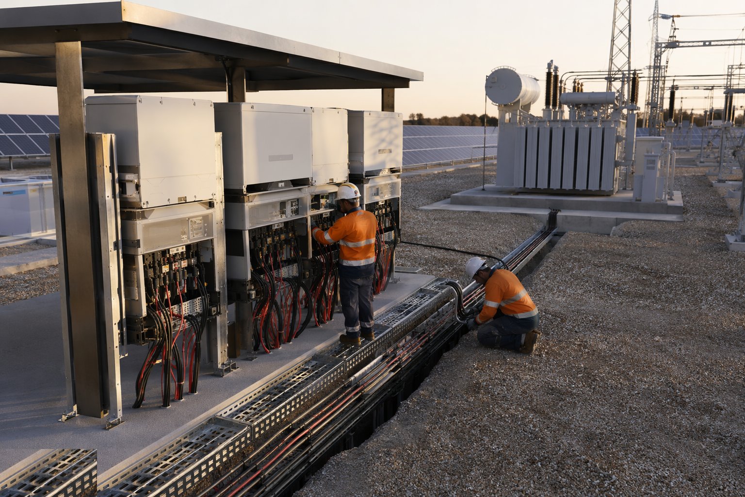
Land the string home runs on the combiner inputs or string inverters from the string register: polarity confirmed, terminations to torque, fuses and isolators verified, and every input labelled. Keep the isolators locked and the dead-front discipline until the commissioning sequence calls for them — the DC side is live in daylight and this is the stage where live field work concentrates. Record as-built string-to-inverter mapping; the SCADA addressing and every future fault trace depend on it.
Step 3: Install inverter stations and MV skids
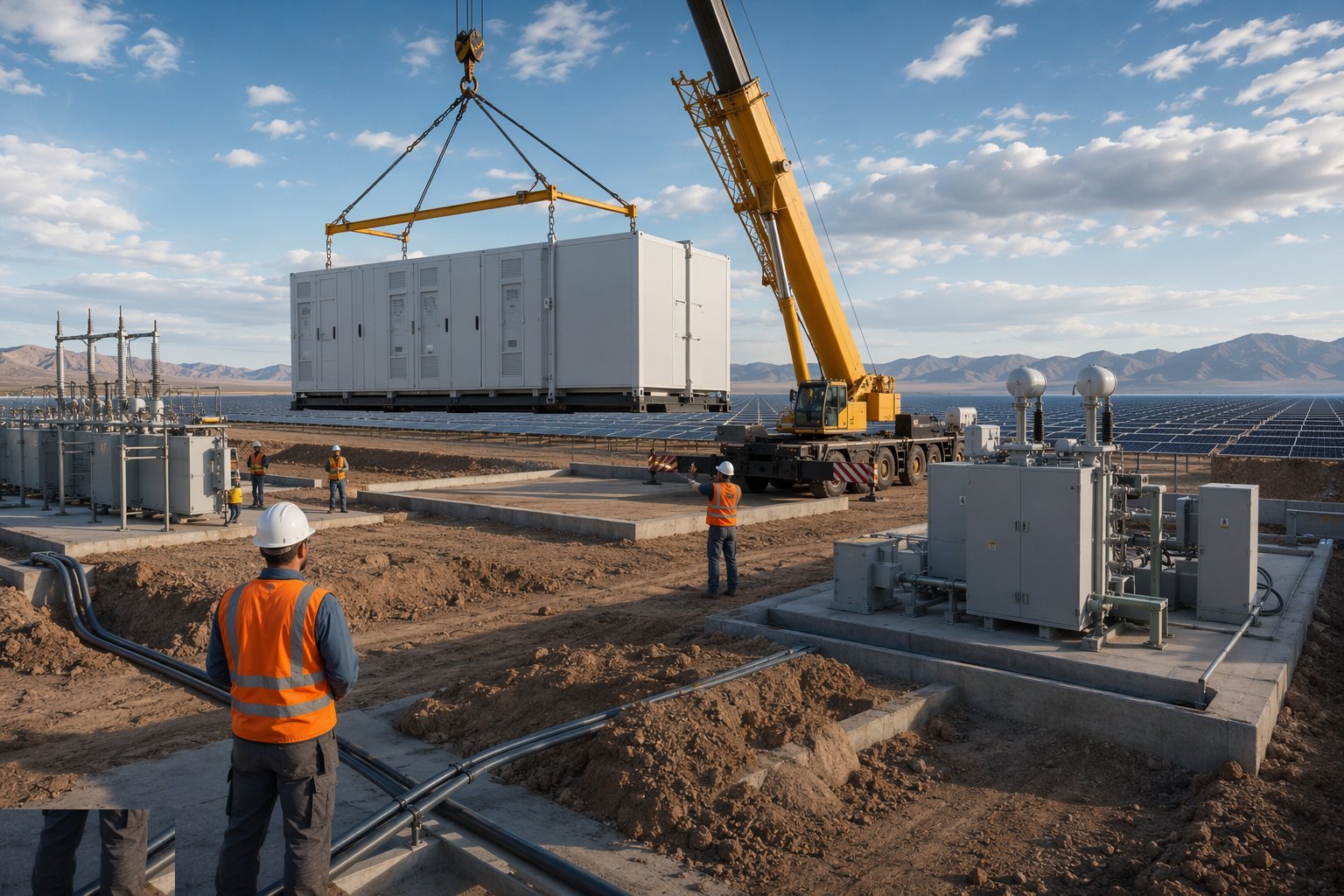
Set the containers, skids and transformers on their pads with the lifts planned and the earthing connections made as they land. Complete the LV and MV terminations inside the stations, the auxiliary supplies, HVAC and ventilation (heavily loaded in Gulf ambient temperatures — station cooling is a derating control, not a comfort feature), and the local protection devices. Factory test certificates travel with each station; site acceptance tests verify what transport and installation may have changed.
Step 4: Pull, joint and test the collector cables
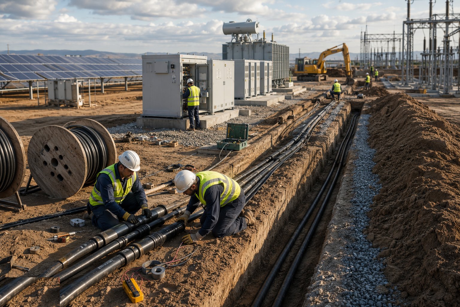
Pull MV and collector cables with tension and bend-radius control, make joints and terminations with qualified jointers under recorded procedures, and bed, tape and backfill in layers with compaction to spec. Test every circuit — insulation resistance, continuity, sheath integrity, phase identification — and record the results against the cable schedule before final backfill. Map every route as-built with GPS; the next decade of excavation permits on this site depends on those records being true.
Step 5: Build and accept the substation
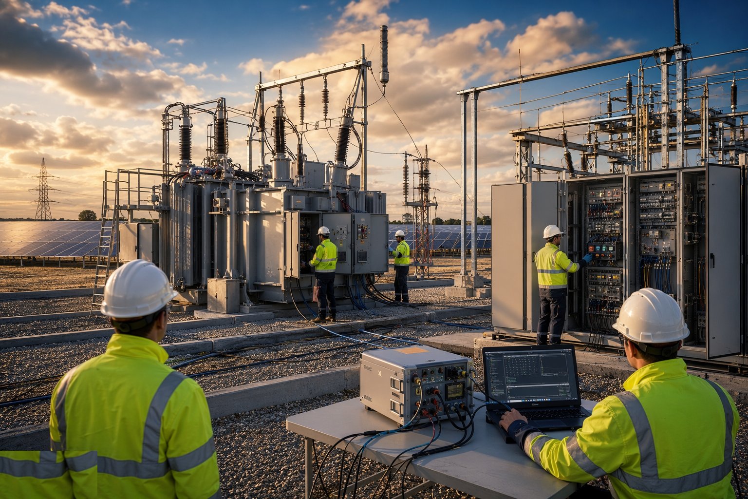
Complete the substation civils, install the switchgear, transformer, protection and metering, and run the package acceptance tests: primary and secondary injection of the protection, intertrip and interlocking checks, transformer commissioning tests, all witnessed per the connection agreement's requirements. This package is on the grid critical path — the protection settings must match the connection agreement to the digit, because the DNO or utility witness engineer will check them against it before permitting energisation.
Step 6: Install and commission SCADA and communications
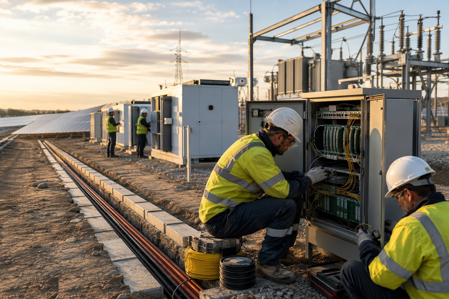
Pull the fibre rings, terminate the network cabinets, and commission the SCADA point by point: inverter data, tracker positions, string currents where monitored, met-station inputs (irradiance, module temperature, soiling sensors), substation values and the alarm matrix. Prove the communications from field device to control screen for every point — a SCADA that shows 90 per cent of the plant is a fault-finding regime for its whole operating life — and set up the export-limitation and grid-code control interfaces the connection agreement requires.
Step 7: Integrate, test and freeze for energisation
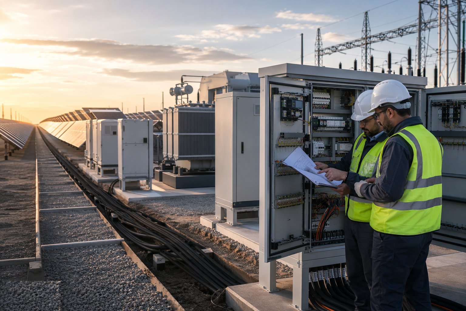
Close the stage with the integrated test regime: DC and AC test records complete, earthing network proven, protection settings signed, SCADA points green, and the pre-energisation punch managed to zero Category A items. Compile the energisation dossier — test certificates, as-built cable maps, protection certificates, witness schedules — because the next stage's grid witnesses will audit it before anyone closes a breaker. The plant is now electrically complete and waiting on one thing: permission to energise.
Plant and equipment
- Trenchers, excavators and cable ploughs for the collector network
- Cable drum trailers, rollers, pullers and tension monitors
- MV jointing kits, crimping tools and qualified jointers' equipment
- Inverter stations, MV skids, transformers and switchgear packages
- VLF and insulation-resistance test sets for MV cables
- Secondary injection test sets for protection commissioning
- Fibre splicing and OTDR test equipment
- Met stations: pyranometers, module temperature and soiling sensors
Quality control checks
- Soil thermal resistivity survey current; cable derating verified for Gulf conditions
- Jointer qualifications and joint records against every MV joint
- Cable test results filed before backfill; routes mapped as-built by GPS
- String-to-inverter mapping recorded; SCADA addressing verified
- Protection settings signed against the connection agreement
- Station FAT/SAT certificates complete; auxiliary cooling proven
- SCADA point-to-point schedule 100 per cent green
- Energisation dossier compiled and audited before grid witness
Safety considerations
- DC strings live in daylight: locked isolators, insulated tools, DC-trained crews
- Trench support and battered excavations across the collector routes
- MV jointing competence controls; no unqualified termination work
- Heavy lifts for transformers and stations — planned lifts, exclusion zones
- Switchroom and substation work under electrical safety rules and permits
- Heat and UV exposure for trench and termination crews in the Gulf summer
- Fibre work: laser and glass-shard controls in the comms cabinets
Common defects
- Cable sized without the soil thermal survey — collector runs hot for the asset's life
- MV joint made by an unqualified jointer — fails in service years later
- Trench backfilled before test records complete — fault found at energisation
- String-to-inverter mapping wrong — SCADA data meaningless, fault tracing blind
- Protection settings drifted from the connection agreement — grid witness fails
- Station cooling undersized — inverters derate every hot afternoon
- Fibre cores swapped — half the field offline at first SCADA poll
- As-built cable routes unmapped — later excavation strikes a live collector
Best suited for
- Strings to inverters, inverters to the substation
- MV skids, switchgear and the SCADA that watches everything
- Trenches and cables stitched across the site
- The electrical work that turns modules into a power station
How long does Electrical Balance of System take?
Typical duration: Typically 4–8 months overlapping module installation, with the substation package and its grid-witnessed tests on the critical path; collector trenching paces the field and is usually phased block by block behind string completion..
Related processes
- Site Access & Enabling Works
- Survey, Ground Investigation & Resource Studies
- Piling & Mounting Structures
- PV Module Installation
- Grid Connection & Energisation
- Wind Turbine Foundations
- Craneage & Tower Erection
- Wind Farm Electrical Infrastructure
- Commissioning & Energisation
- River Diversion & Cofferdams
- Dam & Powerhouse Civils
- Electromechanical Installation
- Impoundment, Commissioning & Handover
- Ground-Source Heat Pumps — Homes & Villas
- Shallow Geothermal — Commercial & District Schemes
- Deep Geothermal Drilling & Wells
- Geothermal Plant, Connection & Commissioning
- Power Generation sector guide
- Utilities & Energy group