CFA — Continuous Flight Auger Piles
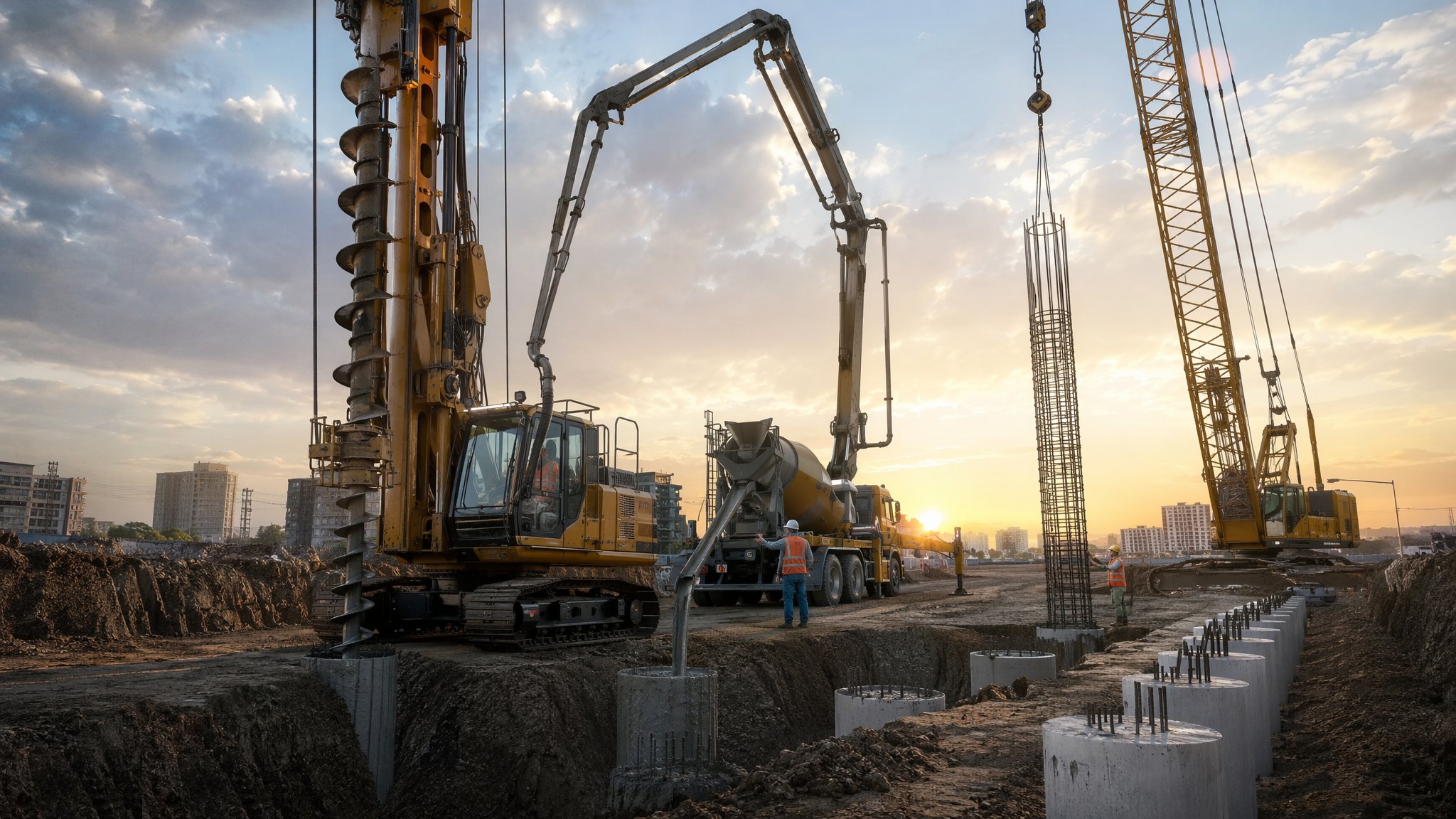
Drill, pump, cage — a cast-in-situ pile formed in one continuous, vibration-free operation.
Last updated 2026-07-28 by the BuildPedia Editorial Team.
What is CFA — Continuous Flight Auger Piles?
Continuous flight auger piling is the urban workhorse of deep foundations. A hollow-stem auger — a continuous helical screw wrapped around a central pipe — rotates into the ground in a single pass to the design depth. Concrete is then pumped down the hollow stem under pressure as the auger is withdrawn at a matched rate, so the bore is filled from the bottom up without ever being left open. A reinforcement cage is pushed or vibrated into the fresh concrete, and the pile is complete: no casing, no drilling fluid, no spoil heaps beyond the auger cuttings, and virtually no vibration.
The method's great strength is also its great risk: nobody ever sees the bore. In a driven pile the hammer proves capacity blow by blow; in a bored pile the hole can be inspected before concreting. In CFA, the only evidence that the pile is sound is the rig's instrumentation trace — depth, torque, auger rotation, concrete pressure, volume placed versus depth — read line by line after the shift. A moment's inattention, an auger lifted faster than the concrete rises, or a pump that stutters in a water-bearing sand layer leaves a neck or a soil inclusion that only shows up weeks later on an integrity test.
CFA earns its place where driven piling cannot go: next to hospitals, laboratories, listed buildings, live railways and completed phases of the same development. In the right ground — firm to stiff clays, silts and made ground above the water table, or below it with disciplined pumping — a single rig installs eight to twelve piles per shift, making it the fastest cast-in-situ method available. In the wrong ground — very soft clays that squeeze, loose saturated sands that flow, or obstructions — it becomes a slow, expensive way to make defective piles, and the design should move to rotary bored or driven methods.
How does CFA — Continuous Flight Auger Piles work, step by step?
Step 1: Set the rig on the surveyed pile position
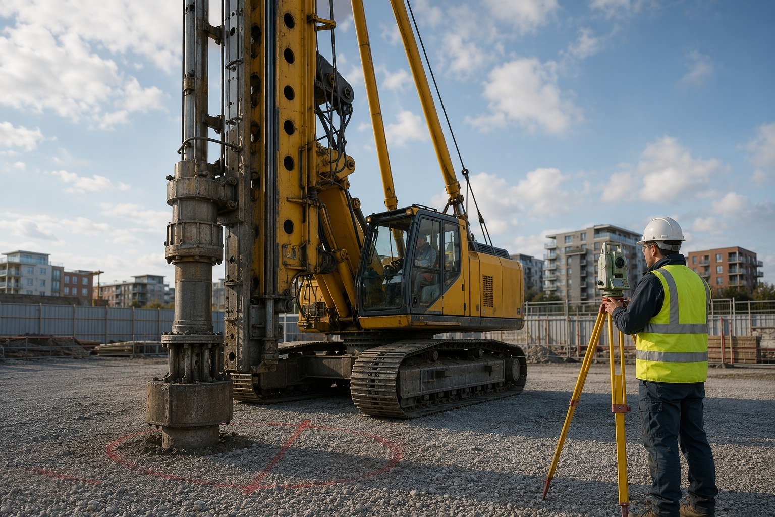
The CFA rig tracks onto the working platform and centres over the pile point, which is checked against the setting-out coordinates before drilling — a pile 100 mm off position can force a pile-cap redesign. Verticality is set from the rig's inclinometers, and the pile reference, design depth and concrete specification are confirmed on the rig log before the auger turns.
Step 2: Auger down to the design depth in one pass
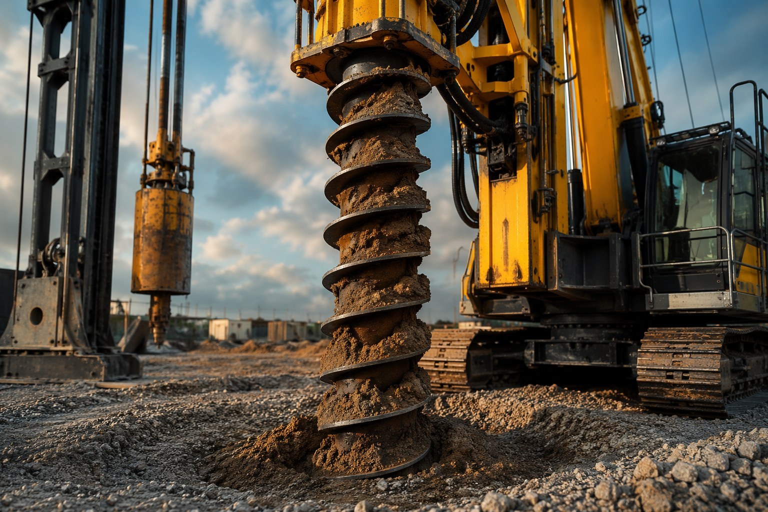
The auger rotates into the ground, soil travelling up the continuous flights to the surface where it is cleared by an attendant excavator. The rig computer logs depth, torque and penetration rate continuously — a soft band or an obstruction shows immediately in the numbers and is checked against the ground investigation. The bore stays supported by the auger itself, so no casing or support fluid is needed.
Step 3: Confirm the toe and start the concrete pump
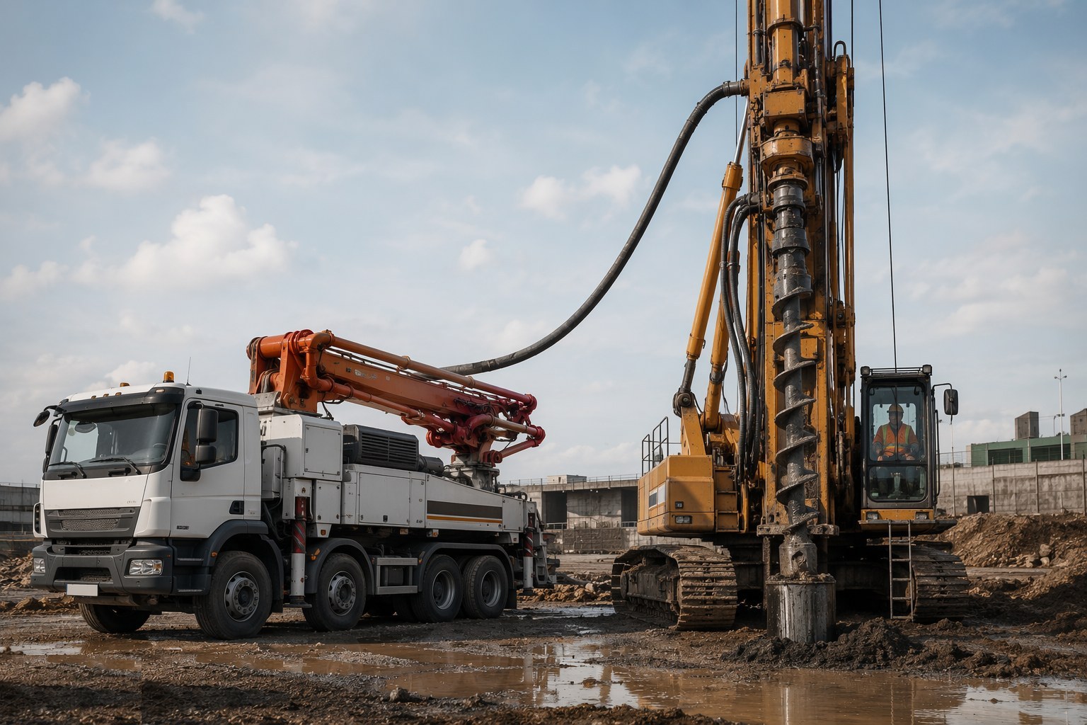
At the target depth the operator confirms the toe from the drilling characteristics — torque and rate against the GI — not from the average of neighbouring piles. The concrete pump charges the line and pressure is built at the auger head, lifting the protective plug at the stem tip. Pumping starts before the auger moves: the concrete head must always stay above the auger base from this moment on.
Step 4: Lift the auger at the matched concrete rate
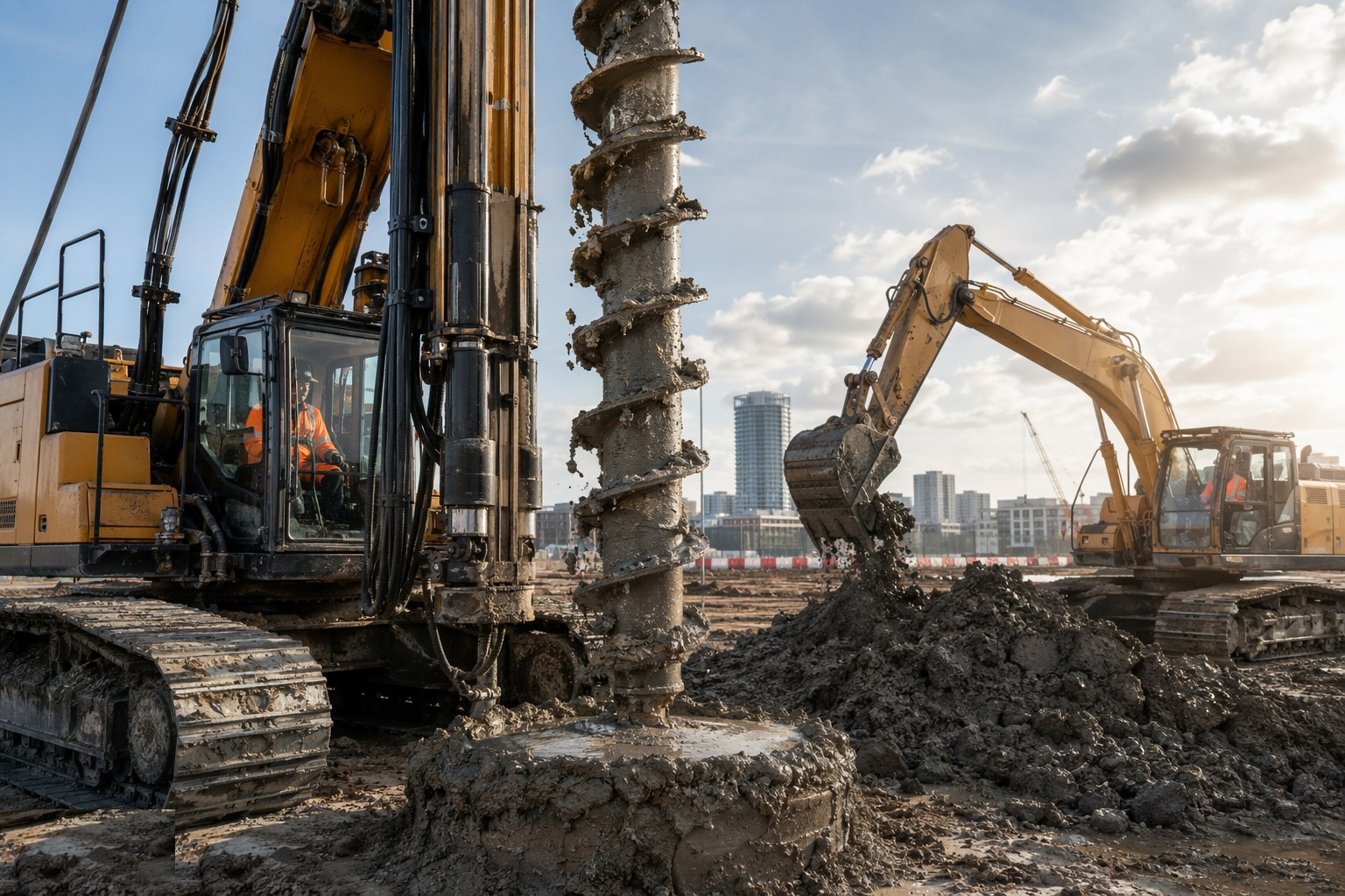
This is the discipline that makes or breaks the pile. The auger is raised slowly — without rotating the soil back down — while concrete is pumped down the stem under positive pressure. The instrumentation plots pressure and volume against depth in real time; if the auger outruns the concrete, the ground collapses into the gap and the pile necks. Over-supply is expected and recorded; under-supply on any metre of depth means investigation.
Step 5: Clear spoil and insert the reinforcement cage
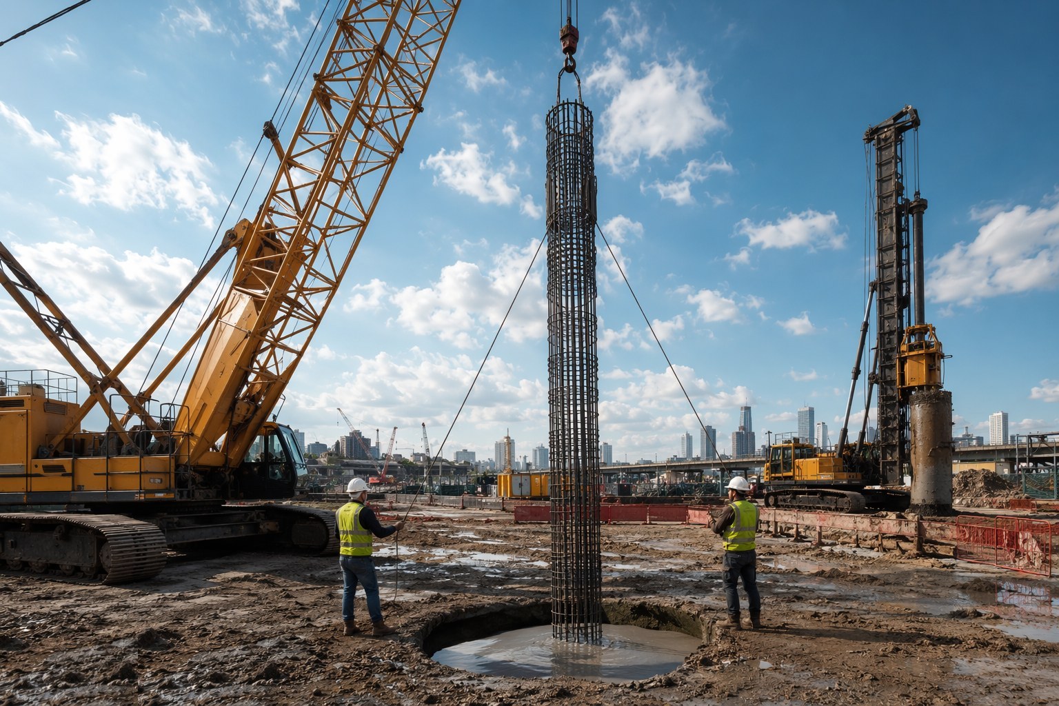
With the auger out, spoil is cleared from around the fresh pile head and a prefabricated cage — checked against the bending schedule, with centralisers for cover — is lowered into the fluid concrete, vibrated down if necessary to reach the design level. Cage length is limited by the fresh-concrete window, which is why cage length and concrete workability are designed together. Depth and orientation are recorded.
Step 6: Log, reconcile and cure
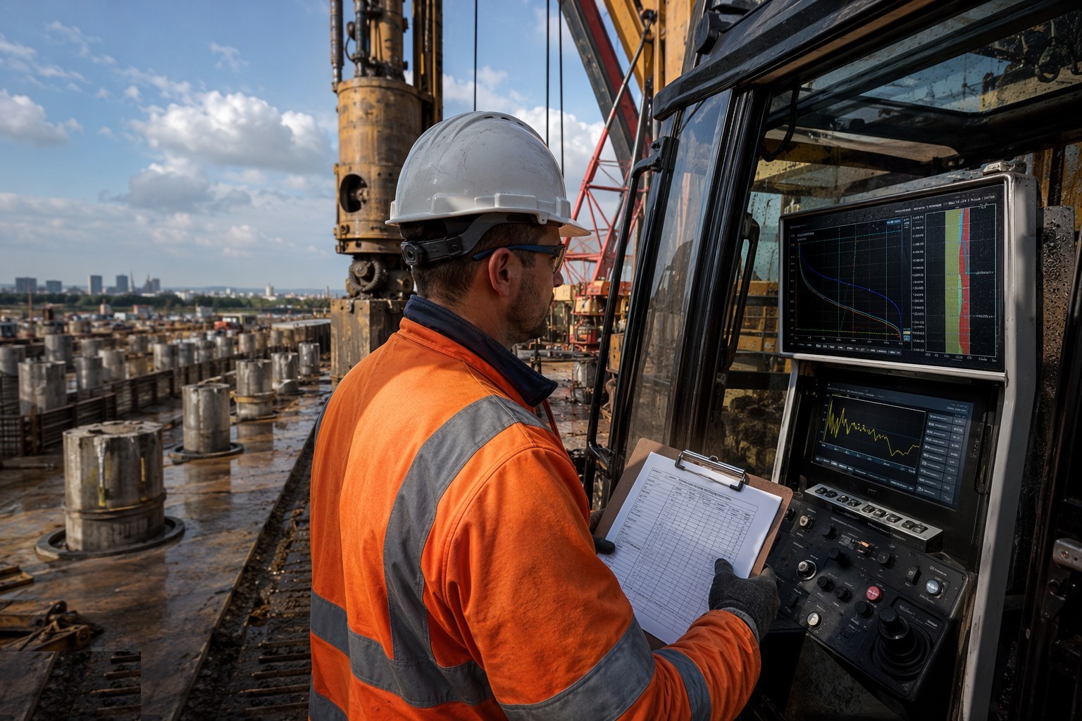
The rig's full trace — depth, torque, pressures, volumes, times — is saved against the pile reference, and the concrete volume placed is reconciled against the theoretical shaft volume. Test cubes are taken from the supply for 7- and 28-day crushing. The pile head is protected and left to cure; nothing is trimmed or loaded until strength is proven.
Step 7: Break down and integrity-test every pile
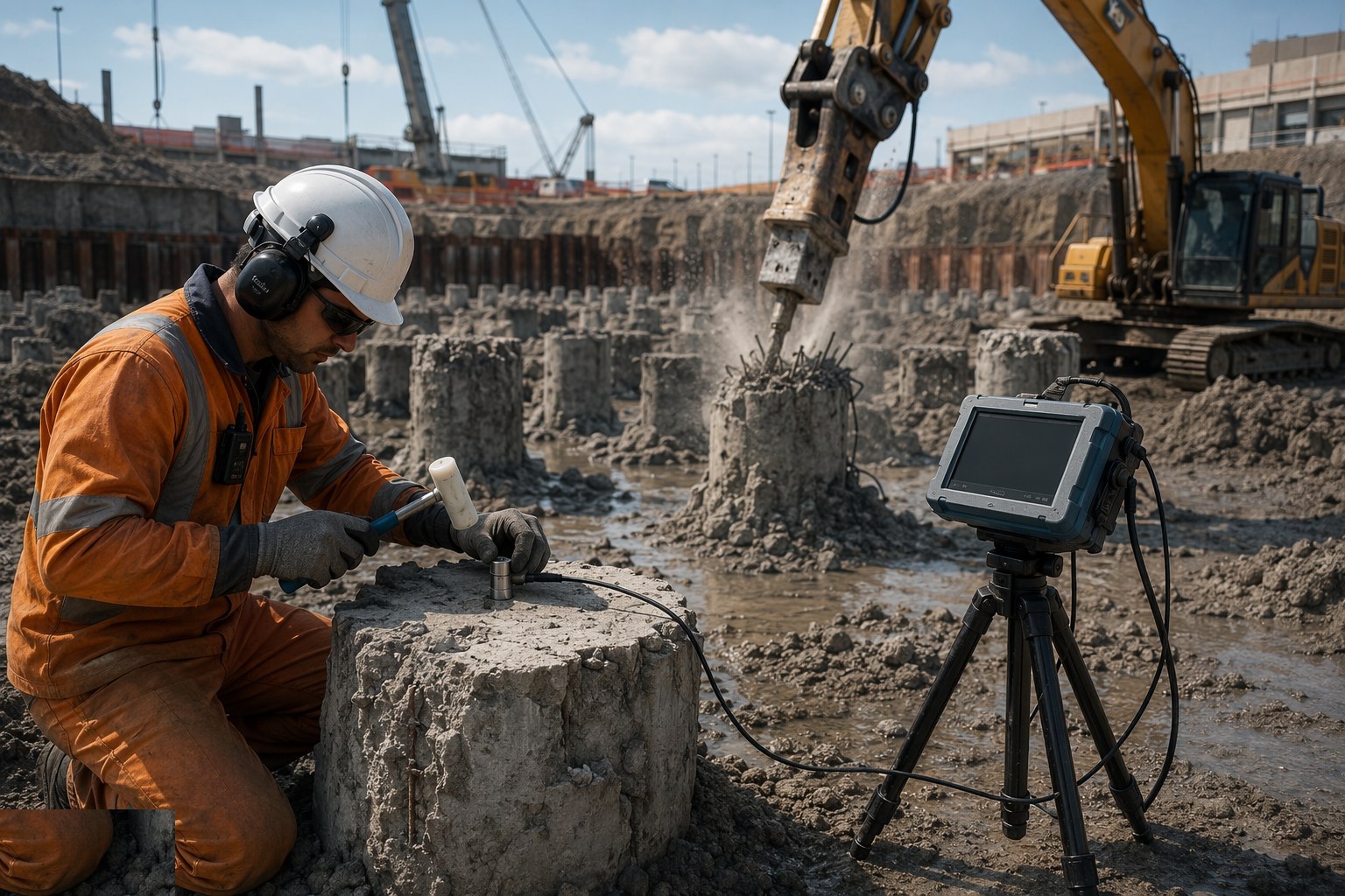
Once cured, piles are broken down to cut-off level, exposing sound concrete for the cap connection. Low-strain sonic integrity testing screens every pile for necking, inclusions and length consistency — cheap, fast and unforgiving. Anomalies trigger coring to recover physical evidence before anyone signs the QA file. Only then do pile caps and ground beams tie the group together.
What are the benefits of CFA — Continuous Flight Auger Piles?
- Fast — 8–12 piles per rig per shift in favourable ground, the quickest cast-in-situ method
- Vibration-free and comparatively quiet — the default choice next to occupied buildings, hospitals and live infrastructure
- Works in loose or water-bearing ground without temporary casing or bentonite support fluid
- Minimal spoil handling — cuttings arrive at the surface clean and self-supporting, with no slurry disposal
- Full instrumentation record on every pile — depth, torque, pressure and volume give an auditable quality trail
- Reinforced like any cast pile — cages handle bending, tension and uplift loads
What are the limitations of CFA — Continuous Flight Auger Piles?
- The bore is never seen — quality depends entirely on operator discipline and rig instrumentation
- Cage length is limited by the fresh-concrete workability window — typically 12 m or less without special measures
- Struggles in very soft clays, flowing sands and ground with obstructions — old foundations can stop the auger outright
- Diameters and depths are modest compared with rotary bored piles — typically 300–900 mm and up to ~25 m
- Sensitive to concrete supply — a pump breakdown or a late truck mid-pour can write off the pile
- Requires a designed, certified working platform — CFA rigs are among the heaviest plant on site
What is CFA — Continuous Flight Auger Piles best suited for?
- Urban sites where noise and vibration rule out driven piling
- Residential and commercial frames on firm to stiff clays, silts and made ground
- Piled foundations next to existing buildings, basements and live railways
- Fast-track programmes needing high daily pile output
- Working loads up to roughly 2,000–3,000 kN per pile
- Sites above or below the water table where the ground will stand for the pour duration
What plant does CFA — Continuous Flight Auger Piles need?
- CFA piling rig with hollow-stem augers and full instrumentation (depth, torque, pressure, volume)
- Concrete pump and dedicated supply line to the rig
- Readymix trucks on a guaranteed continuous supply schedule
- Attendant excavator for spoil clearance and cage handling
- Cage fabrication area — bending schedule, tying and centralisers
- Vibrator for cage insertion into fresh concrete
How is CFA — Continuous Flight Auger Piles quality-checked?
- Rig instrumentation trace reviewed pile by pile — depth, torque, concrete pressure and volume against depth
- Concrete volume reconciliation: placed versus theoretical shaft volume, every pile
- Slump or flow test on each load against the ordered consistence — high-workability mix held for the cage window
- Cube or cylinder samples crushed at 7 and 28 days
- Low-strain sonic integrity testing on every pile; coring of any anomaly
- Pile position and verticality survey against the setting-out, before and after installation
Related processes
- Piling & Deep Foundations — full process guide
- Driven precast concrete piles — method
- Driven steel tube and H piles — method
- Rotary bored cast-in-situ piles — method
- Mini and micro piling — method
- Sheet piling — method
- Site Access & Enabling Works
- Site Clearance & Demolition
- Setting Out & Survey Control
- Earthworks & Excavation
- Dewatering & Groundwater Control
- Shallow Foundations
- Basement & Substructure
- Waterproofing and Tanking
- Concrete Frame Construction
- Steel Frame Construction
- Masonry & Timber Frame
- Floor Slabs & Screeds
- Roofing
- Façade & Cladding
- Insulation Systems
- Windows, Doors & Glazing
- MEP First Fix
- Internal Finishes
- MEP Second Fix & Commissioning