Rotary bored cast-in-situ piles
Big diameters, rock sockets and total control — the inspectable pile for the heaviest loads.
Last updated 2026-07-28 by the BuildPedia Editorial Team.
What is Rotary bored cast-in-situ piles?
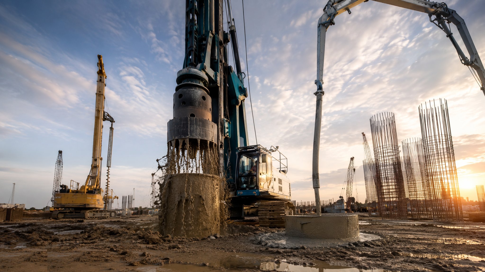
Rotary bored piling is the most controllable deep foundation method there is. A powerful rotary rig bores a circular hole — from 450 mm to two metres and beyond — using augers, buckets or coring tools, supporting the bore where necessary with temporary casing or bentonite/polymer fluid. Unlike CFA, the hole can be inspected: the arisings are sampled stratum by stratum, the toe is verified against the GI, and on dry shafts an engineer can literally be lowered to look at the base. Then the cage goes in and concrete is placed by tremie from the bottom up. Every stage is visible, measurable and correctable.
This is the method for the loads nothing else can carry: tower cores, transfer structures, bridges and heavy plant, with single-pile working loads well beyond 5,000 kN and rock sockets where the design needs them. It handles hard strata, obstructions can be cored or chiselled through, and depth is essentially limited only by the rig. The trade is speed and cost: two to six piles per rig per shift rather than CFA's ten, plus casing, support-fluid handling, spoil by the grab-load and a heavy logistics train.
The method's inspectability is real but not automatic — it has to be enforced. The classic bored-pile defects are housekeeping defects: debris or slurry left at the toe (the soft toe), support fluid contaminated past its specification, a tremie mouth lifted out of the concrete mid-pour letting slurry fold into the shaft, or a bore left open too long so the sides relax. The discipline is a checklist culture: bore log, base cleanliness check, fluid tests, volume reconciliation and a continuous pour — every pile, no exceptions.
How does Rotary bored cast-in-situ piles work, step by step?
Step 1: Set up on the casing and verify position
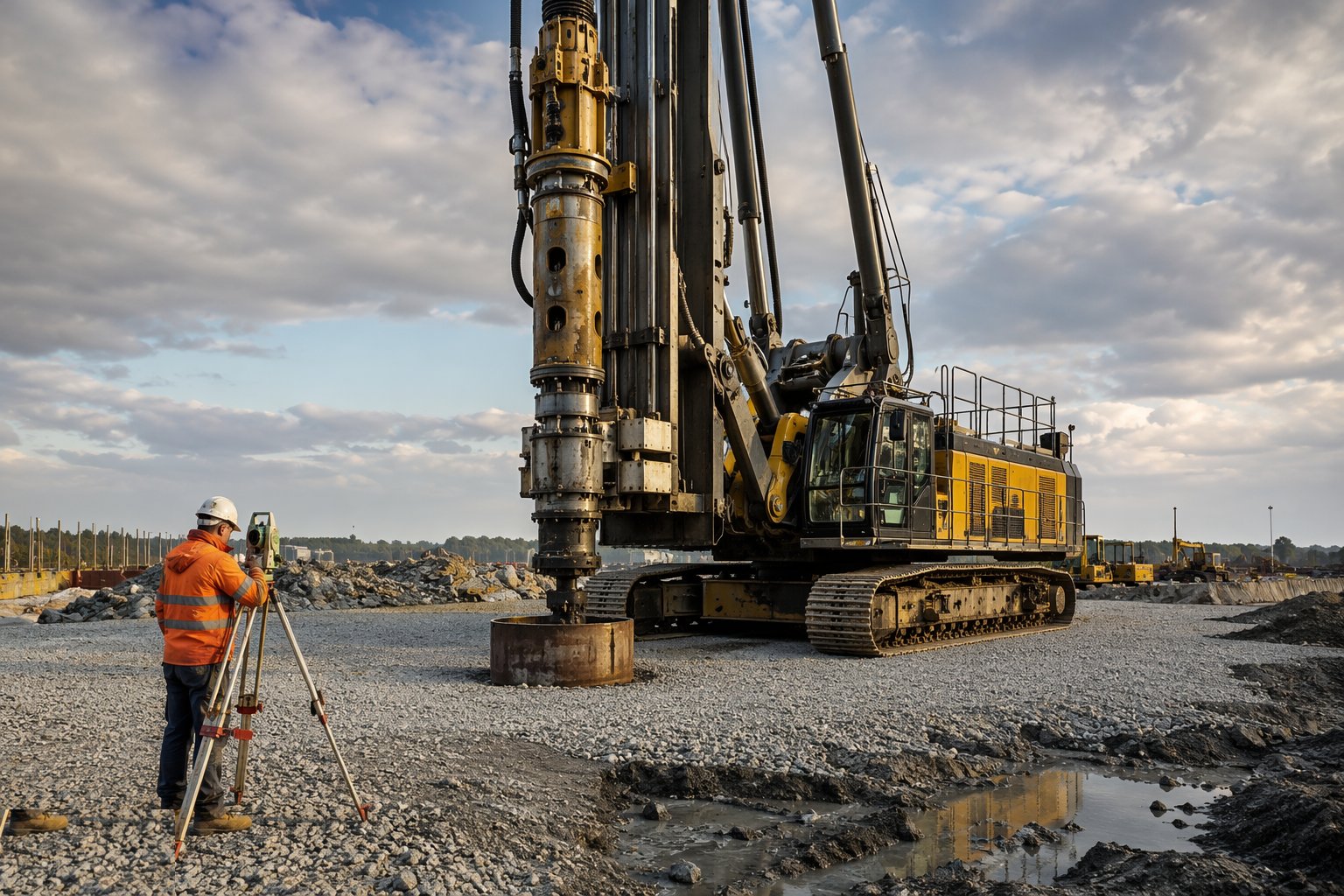
The rig centres over the surveyed pile point and the first section of casing is pitched and plumb-checked — the casing sets the pile's position and verticality, so it is checked before the tool turns. Pile reference, design depth, toe stratum and concrete specification are confirmed on the bore log.
Step 2: Bore with stratum logging
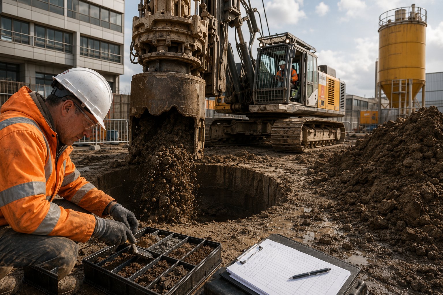
The auger or bucket advances in passes, with arisings sampled and logged against the GI at every change of stratum. In unstable or water-bearing ground the bore advances under temporary casing or support fluid, whose density, viscosity, sand content and pH are tested against specification — fluid outside spec is replaced, not excused.
Step 3: Verify and clean the toe — the hold point
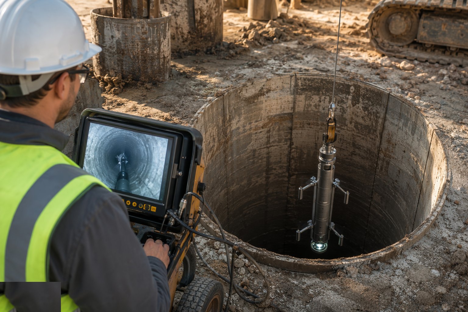
At design depth the toe is confirmed from drilling characteristics and arisings against the GI, and the base is cleaned — airlift or clean-out bucket — until the cleanliness standard is met. Depth is measured and recorded; on dry shafts the base can be inspected directly. A soft toe is a capacity failure designed in, so this step stops the job until it is signed.
Step 4: Lower the reinforcement cage
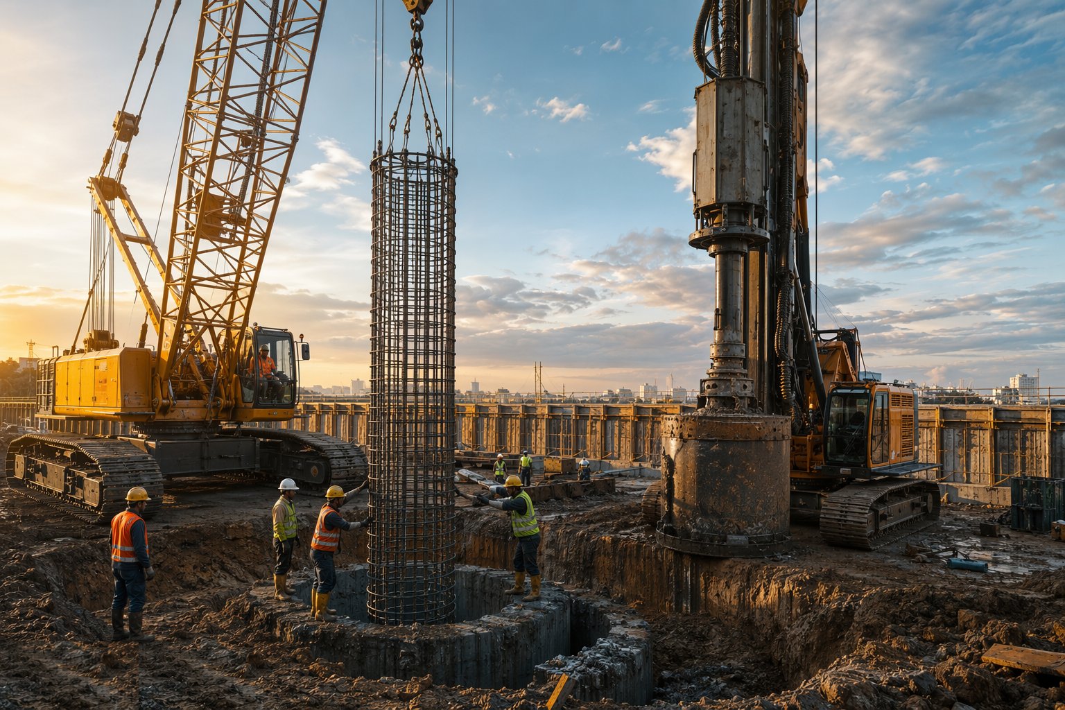
The prefabricated cage — checked against the bending schedule, with centralisers for cover and cross-hole sonic logging tubes on critical piles — is lowered in sections, spliced as designed, and set to level. The cage is hung from the casing so it cannot sink or float during the pour, and the top level is recorded.
Step 5: Tremie the concrete from the bottom up
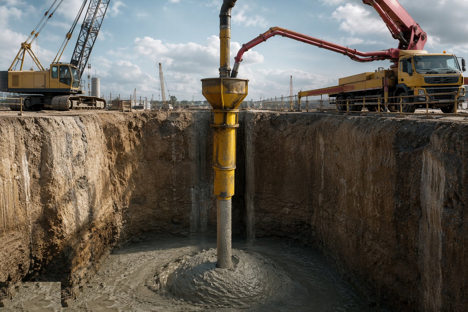
Concrete is placed through a tremie pipe whose mouth stays buried in fresh concrete at all times — the rising column displaces the support fluid upward without mixing. The pour is continuous; volume placed is plotted against depth and reconciled with the theoretical shaft volume. A tremie seal lost mid-pour means re-establishing by the book, or the pile goes into the investigation file.
Step 6: Extract the casing and protect the head
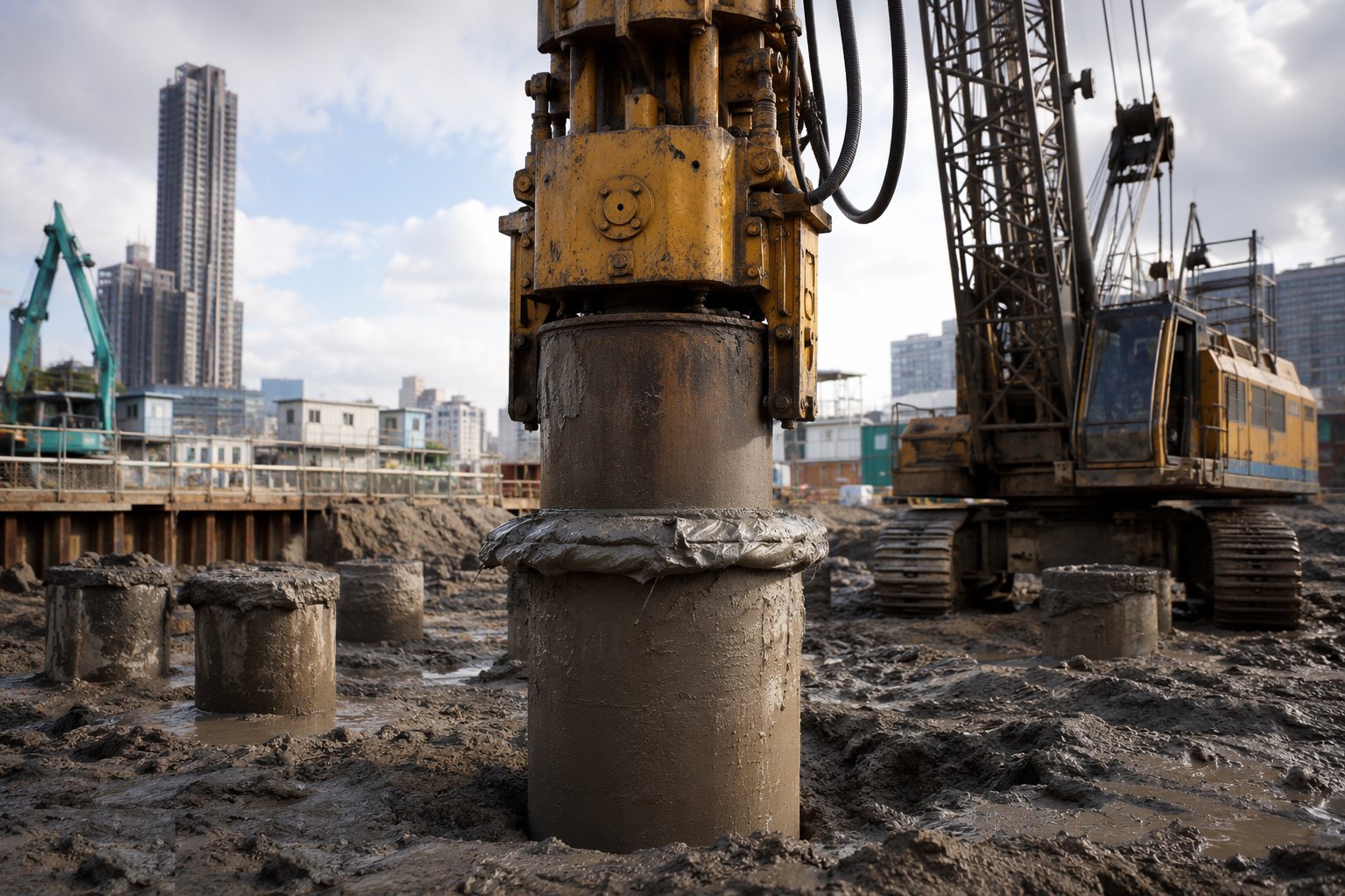
Temporary casing is withdrawn as the concrete rises, keeping the concrete head always above the casing toe and above any water level — lift the casing faster than the concrete and the shaft necks. The pile is concreted above cut-off to displace contaminated material, then capped and protected for curing.
Step 7: Test integrity and capacity
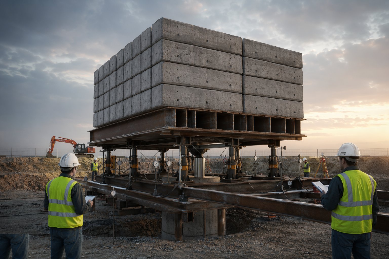
Low-strain integrity tests screen the shaft; cross-hole sonic logging through the pre-installed tubes maps concrete quality between tubes on large or critical piles; anomalies are cored. Static load tests on preliminary piles prove the design. Bore logs, fluid tests, pour records and test results close the QA file.
What are the benefits of Rotary bored cast-in-situ piles?
- Very high capacities — the largest diameters and deepest piles on the market, with rock sockets
- Inspectable at every stage — arisings, toe, fluid and pour are all verifiable
- Handles hard strata and obstructions — coring and chiselling keep going where augers stop
- Low noise and vibration — suits urban sites with heavy loads
- Full-depth cages and flexible lengths — bending, tension and uplift all covered
What are the limitations of Rotary bored cast-in-situ piles?
- Slow and expensive — a fraction of CFA output with a much heavier logistics train
- Spoil, casing and support-fluid handling dominate site housekeeping and cost
- Support fluid is a quality risk in itself — specification and disposal both matter
- Open-bore time is limited — ground relaxation and collapse windows demand discipline
- Tremie placement is skilled work — a lost seal mid-pour is a serious defect
What is Rotary bored cast-in-situ piles best suited for?
- Towers, cores, transfer structures and bridges with very high single-pile loads
- Hard strata, rock sockets and ground with obstructions
- Deep piles beyond CFA or precast capability
- Urban sites needing low vibration but heavy capacity
- Marine and river works with cased bores
What plant does Rotary bored cast-in-situ piles need?
- Rotary bored piling rig with augers, buckets, coring barrels and casing oscillator
- Temporary casing sections with oscillating or vibratory extraction
- Bentonite/polymer plant: mixing tanks, pumps, desanding and testing kit
- Crawler crane for long cage handling
- Tremie pipes, hoppers and concrete pump with guaranteed supply
- Airlift and clean-out equipment for base cleaning; spoil skips and licensed disposal route
How is Rotary bored cast-in-situ piles quality-checked?
- Bore log per pile: strata, depths, water strikes, tool changes
- Base cleanliness and toe verification as a recorded hold point
- Support fluid tests — density, viscosity, sand content, pH — before and during concreting
- Tremie pour record: continuous operation, mouth embedment, volume versus depth reconciliation
- Cage check against bending schedule with cover centralisers; top level recorded
- Integrity tests on all piles; CSL on critical piles; coring of anomalies; static load tests on preliminaries
Related processes
- Piling & Deep Foundations — full process guide
- CFA — Continuous Flight Auger Piles — method
- Driven precast concrete piles — method
- Driven steel tube and H piles — method
- Mini and micro piling — method
- Sheet piling — method
- Site Access & Enabling Works
- Site Clearance & Demolition
- Setting Out & Survey Control
- Earthworks & Excavation
- Dewatering & Groundwater Control
- Shallow Foundations
- Basement & Substructure
- Waterproofing and Tanking
- Concrete Frame Construction
- Steel Frame Construction
- Masonry & Timber Frame
- Floor Slabs & Screeds
- Roofing
- Façade & Cladding
- Insulation Systems
- Windows, Doors & Glazing
- MEP First Fix
- Internal Finishes
- MEP Second Fix & Commissioning