Radon protection
A continuous barrier between the ground and the building, plus a way of venting the gas below it if it is ever needed.
Last updated 2026-09-05
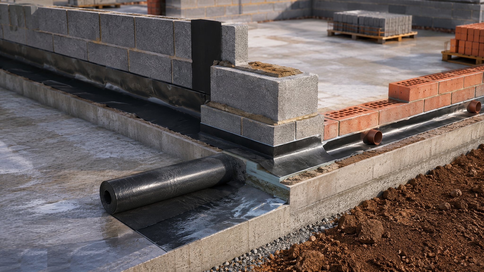
What is Radon protection?
Radon is a naturally occurring radioactive gas produced by the decay of uranium in rocks and soils. It is colourless and odourless, it moves through the ground, and it enters buildings through gaps in the floor construction - cracks, service penetrations, the joint between floor and wall, and any opening into an underfloor void. Outdoors it disperses harmlessly. Indoors it can accumulate, and long-term exposure to elevated indoor concentrations is associated with an increased risk of lung cancer. That is the whole reason the trade exists: the gas is a health matter rather than a building fabric one, and the building work exists to keep it out of the occupied space.
Whether protection is required, and how much, depends on where the building is. Radon potential has been mapped from geology and from measurements in existing buildings, and those maps divide the country into areas where no protective measures are needed, areas where basic protection applies, and areas where full protection applies. The designer establishes which category the site falls into and specifies accordingly - it is not a judgement made from the ground conditions seen in a trial pit. In broad terms, basic protection means a continuous gas-resistant barrier across the whole footprint of the building, and full protection means that barrier plus a means of ventilating the ground beneath the floor, either passively or by a fan that can be brought into use later.
Everything then turns on workmanship. A radon barrier is only as good as its least careful junction. The sheet material itself is rarely the problem; the problems are at the laps, at the perimeter where the barrier meets the wall construction or the damp proof course, at every service penetration, at internal corners and at the places where a following trade has walked over it, dropped something on it or cut it to get a pipe through. A membrane with a single unsealed penetration is not a partial barrier - it is a route for the gas, and the pressure difference between the ground and the heated building actively draws air through it. This is why radon protection is inspected before it is covered and why the inspection has to be taken seriously by somebody who understands what they are looking at.
How does Radon protection work, step by step?
- 1
Step 1: Establish the radon category for the site
The designer checks the site against the published radon potential mapping and establishes whether the building needs no measures, basic protection or full protection. For an individual site the answer can be refined by a site-specific report. The category is recorded and drives the specification: the barrier requirement, whether a sub-floor ventilation provision is needed, and whether that provision has to be capable of being made active later. On a project with several plots or several buildings the category applies to the location rather than the building type, so an outbuilding on the same site attracts the same consideration as the house.
- 2
Step 2: Design the barrier as a continuous envelope
The barrier has to be continuous across the entire ground floor and continuous with the wall damp proofing, so that there is no path from the ground into the building at any point. That means it is designed rather than assembled on the day: the designer or the membrane supplier produces details for the perimeter junction, for internal walls that pass through the floor, for changes in floor level, for column bases, for the tops of any underfloor voids and for every service entry. Getting these details on paper before the concrete gang arrives is what separates a barrier that works from one that merely exists. The gas-resistant membrane specified is a purpose-made product, not simply a heavier damp proof membrane, and the designer chooses it against the category and the floor construction.
- 3
Step 3: Prepare the substrate and lay the membrane
The surface the membrane sits on is prepared so that it will not damage it - blinded, swept clean, free of protruding stone, reinforcement ends, nails and formwork debris. Protection layers above and below are used where the specification calls for them. The membrane is then laid out across the full footprint with the laps running in the arrangement the designer has specified and with enough material left at the perimeter and at every upstand to make the junctions properly. It is unrolled rather than dragged, and it is not laid in weather that will trap water beneath it or make the sealing tapes fail.
- 4
Step 4: Seal the laps and the junctions
Laps are sealed with the tapes, welds or jointing system the membrane manufacturer supplies, on clean, dry surfaces, with the lap width the manufacturer specifies. The perimeter is dressed up and lapped into the wall damp proof course so that the horizontal barrier and the vertical barrier form one envelope. Internal corners, external corners and step details are made with preformed components rather than folded and taped on site wherever the manufacturer provides them. Every one of these junctions is a place where the barrier can fail, and every one of them is easier to get right on the day than to find and repair afterwards.
- 5
Step 5: Seal every service penetration
Drainage, water, gas, electrical and telecoms entries all pass through the barrier, and each one is sealed with a purpose-made collar or top hat bonded to the membrane. Penetrations are set out and formed in the right place first time, because a pipe that is moved after the membrane is sealed leaves a hole that has to be patched. Service entries are the most common point of failure in the whole installation, so they are inspected individually and photographed before they are covered. Where a service entry has to be formed after the membrane is down, it is treated as a formal repair with the manufacturer's detail rather than a bit of tape.
- 6
Step 6: Provide sub-floor ventilation where full protection applies
Where full protection is specified, the barrier is supplemented by a means of removing gas from beneath the floor before it can reach the building. Suspended floors are commonly ventilated by cross-ventilating the underfloor void through the external walls. Ground-bearing floors are commonly provided with a sump or a network of perforated pipework within the granular fill below the slab, connected to a sealed riser that terminates above the roof. On most projects that riser is installed passively at construction and left capable of being connected to a fan later, so that if post-completion testing shows the barrier alone is not enough, the system can be made active without opening the floor. The extent, the position and the number of these provisions come from the designer.
- 7
Step 7: Inspect and protect before covering
The completed barrier is inspected across its whole area before anything is placed on it - laps, perimeter, corners, upstands and every penetration - and the inspection is recorded with photographs. It is then protected from the trades that follow, because reinforcement mesh, scaffold feet, wheelbarrows, dropped tools and concrete boots all damage membranes and the damage is invisible from the moment the pour starts. Damage found before covering is repaired to the manufacturer's detail. Damage found after covering usually cannot be repaired at all, which is why the hold point before the pour is the most valuable single control on the job.
- 8
Step 8: Test after completion and act on the result
The only way to know whether the measures have worked is to measure radon in the finished building. Testing is carried out with detectors placed in occupied rooms over an extended period, because radon concentrations vary with the weather, the season and how the building is used, so a short measurement proves very little. The results are assessed by the testing organisation against the published guidance. If the concentration is higher than it should be, the pre-installed sub-floor system is the remedy - the fan is fitted, the system is commissioned and the building is re-tested. That is exactly why the passive provision was installed in the first place.
What are the benefits of Radon protection?
- Addresses a genuine long-term health risk with materials and workmanship the ground floor already needs
- A gas-resistant barrier doubles as the damp proof membrane, so much of the cost is displaced rather than added
- Installed with the floor construction, so the marginal cost at build stage is very small compared with retrofitting
- A passive sub-floor system installed at construction can be made active later without breaking into the finished floor
- The result is measurable - post-completion testing gives the occupier evidence rather than assurance
- The same detailing discipline improves airtightness and resistance to other ground gases
What are the limitations of Radon protection?
- Wholly dependent on workmanship - one unsealed penetration or one torn lap can undo the whole installation
- Almost impossible to inspect or repair once the slab is poured and the floor is finished
- Easily damaged by following trades, so protection and a hold point before covering are essential rather than optional
- Applies only where the mapping shows a need, and the category comes from the designer rather than from anything visible on site
- Meaningful testing takes an extended period, so the result arrives well after the building is occupied
- An active sub-floor system running later brings a fan, a power supply, running costs and a maintenance obligation
- A barrier alone does not always achieve the required indoor concentration, which is why the sub-floor provision is designed in from the start
What is Radon protection best suited for?
What plant does Radon protection need?
- Purpose-made gas-resistant membrane in the grade the designer has specified, with its matching tapes, welds and sealing system
- Preformed corner units, top hats and pipe collars from the same manufacturer
- Protection layers, geotextiles or sand blinding above and below the membrane where specified
- Perforated sub-floor pipework, sump units and granular fill for the ventilation provision
- Sealed riser pipework to roof level, with provision for a fan to be fitted later
- Underfloor ventilator units and ducts where a suspended floor is cross-ventilated
- Radon detectors for post-completion testing, placed and assessed by a testing organisation
How is Radon protection quality-checked?
- Radon category for the site established by the designer and recorded before the floor is designed
- Junction, perimeter, corner and penetration details issued on drawings before the membrane is ordered
- Substrate inspected and confirmed clean and free of anything that would puncture the membrane
- Lap widths and the sealing system checked against the manufacturer's requirements, on clean dry surfaces
- Perimeter lapped into the wall damp proof course to form one continuous envelope, and inspected as such
- Every service penetration inspected and photographed individually before covering
- Formal hold point and full-area inspection before any reinforcement, concrete or screed is placed
- Barrier protected from following trades, with any damage repaired to the manufacturer's detail and re-inspected
- Sub-floor ventilation provision installed, its position recorded, and the riser left capable of being made active
- Post-completion testing carried out over an extended period and the result issued to the occupier, with remedial activation of the sub-floor system where required
Back to process
Damp Proofing - DPC, DPM and Cavity Trays