Heat networks, cooling plants and multi-utility corridors - shared infrastructure for whole districts.
District energy is a power station broken into pieces and spread under the streets: energy centres holding the plant, insulated pipe networks running beneath the roads, and connections into every building on the scheme. The corridor civils - access, earthworks, drainage and the ground-source arrays that feed the network - are the shared methods, linked below from the transport and power-generation sectors.
The process map - 3 guides
Each one is a full guide: overview, variants, numbered steps, plant, testing, safety and defects.
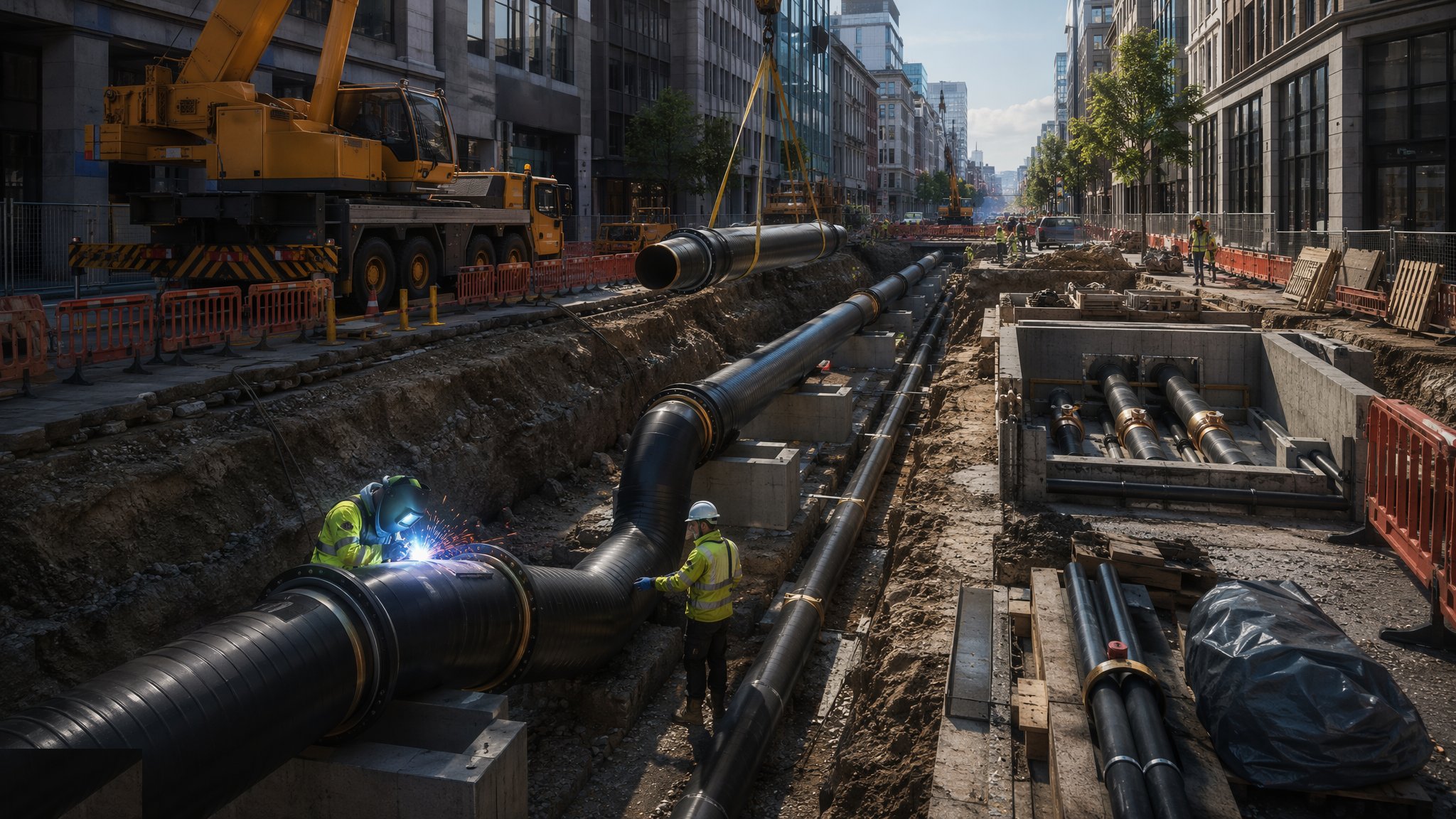
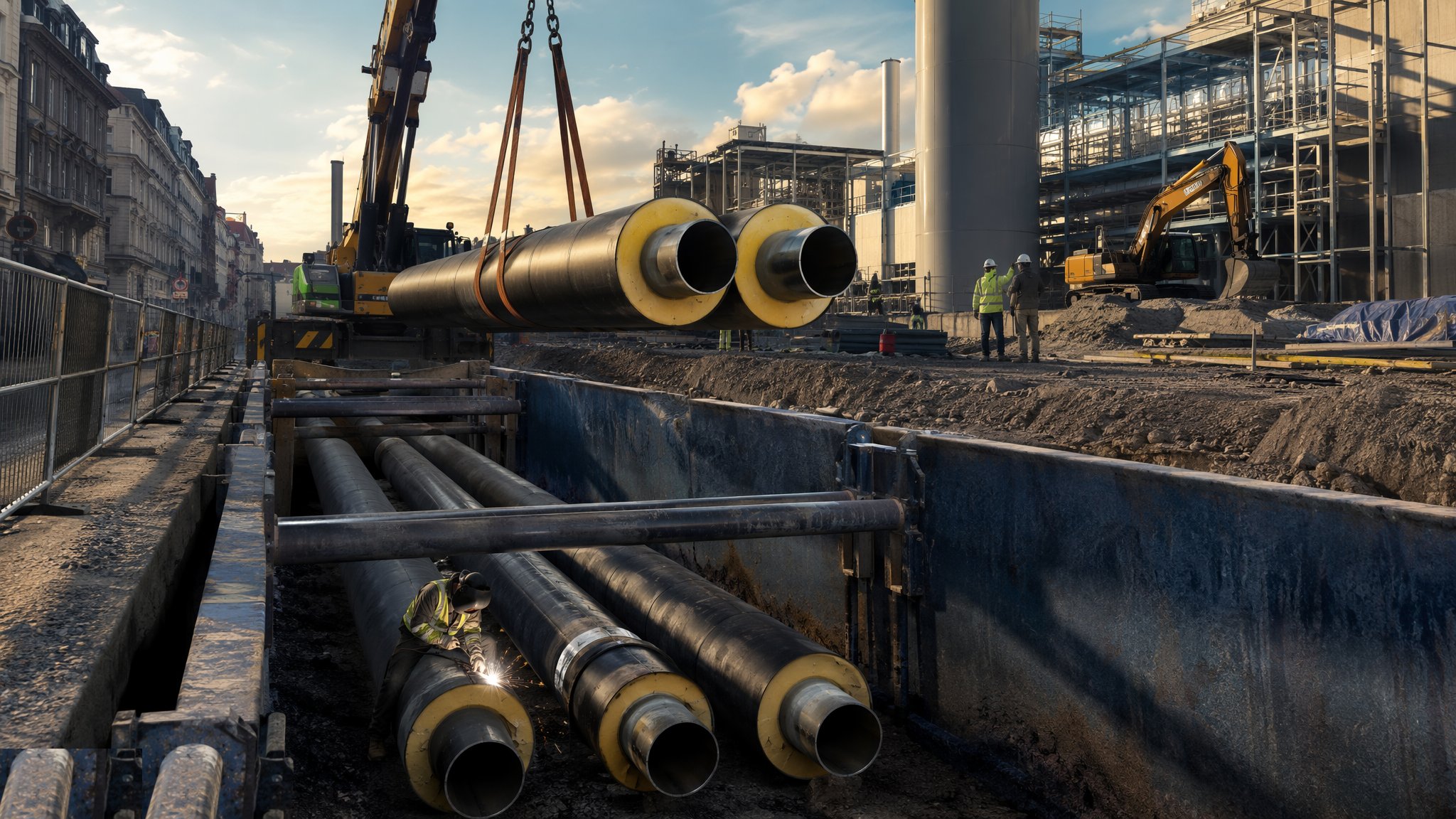
District Heating & Cooling Networks
Mains of pre-insulated bonded pipe welded end to end through live streets, carrying hot or chilled water under the city - a heat network that only works if every joint, anchor and expansion loop is exactly where the design put it.
Open process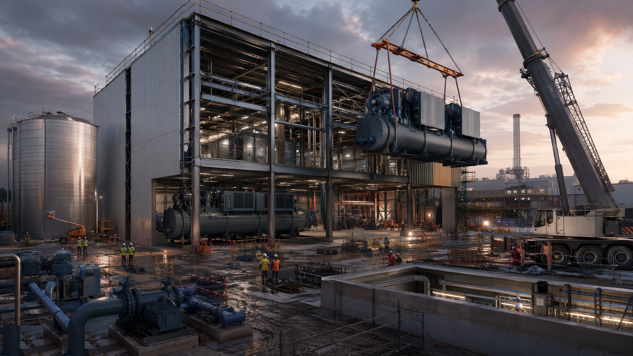
Energy Centre Construction
The plant room that heats or cools a district - boilers or chillers the size of buses, thermal stores, flues, pumps and a BMS to conduct them - installed, connected and brought online one customer at a time.
Open process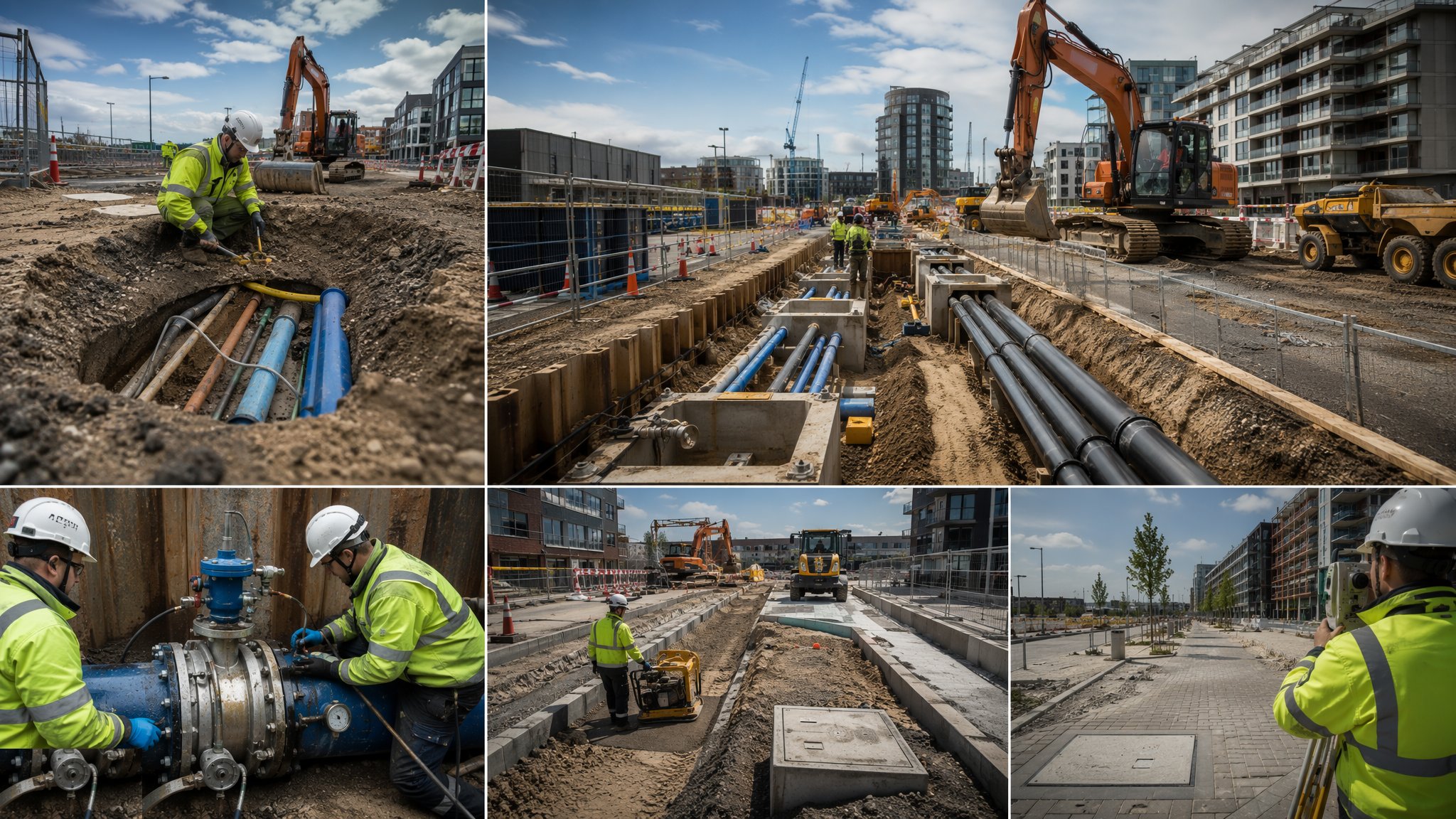
Utility Diversions & Connections
Moving other people's live services out of the way of the development - trial holes, statutory notices, diversion trenches and live-to-live connections - the unglamorous enabling works that decide when everything else can start.
Open processShared methods used in this sector
These guides are owned by other sectors - the canonical page lives there - but the method is the same here. Cards open the guide at its home sector.
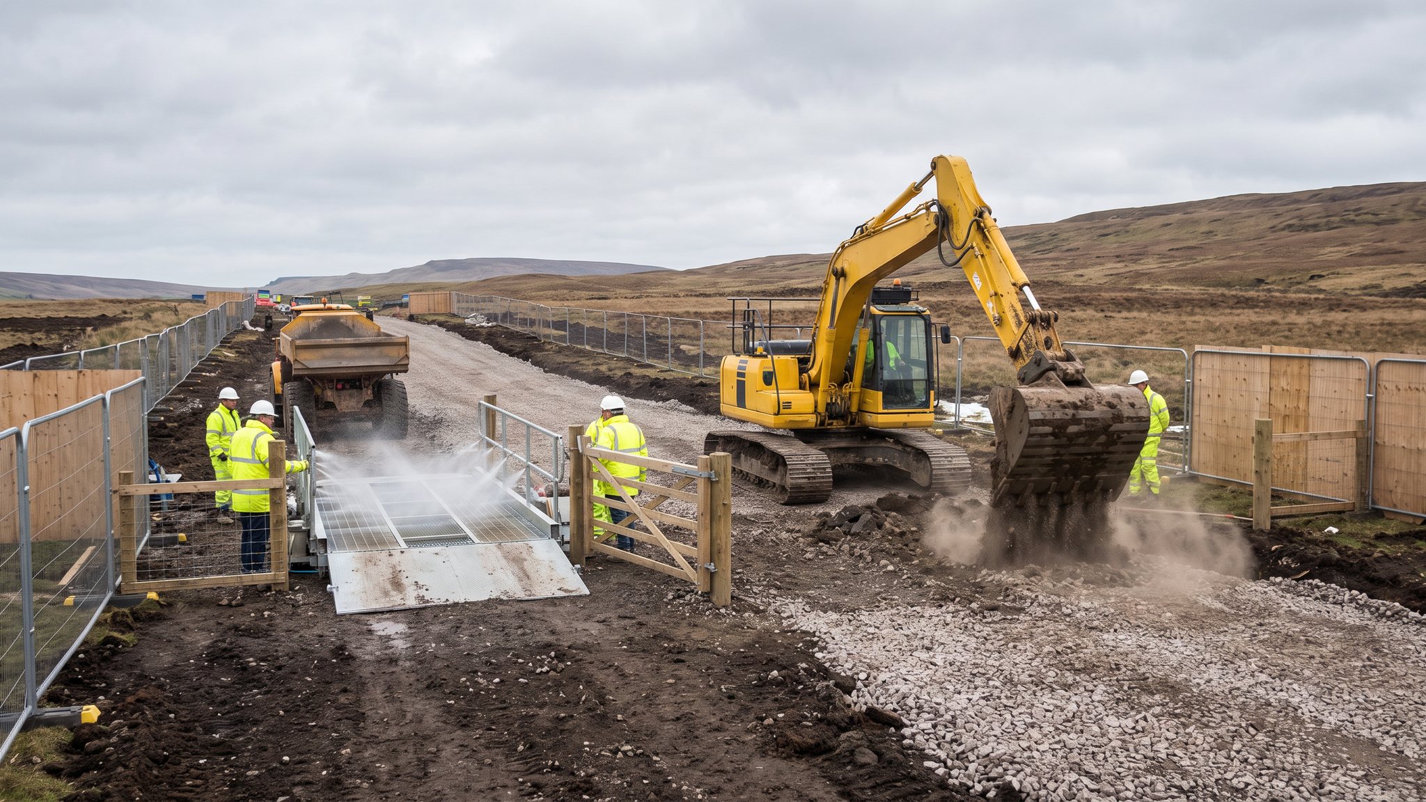
Corridor Access & Enabling Works
Turning a length of route - often a live highway - into a controlled, approved, workable construction corridor.
Open processCanonical guide: Roads & Highways
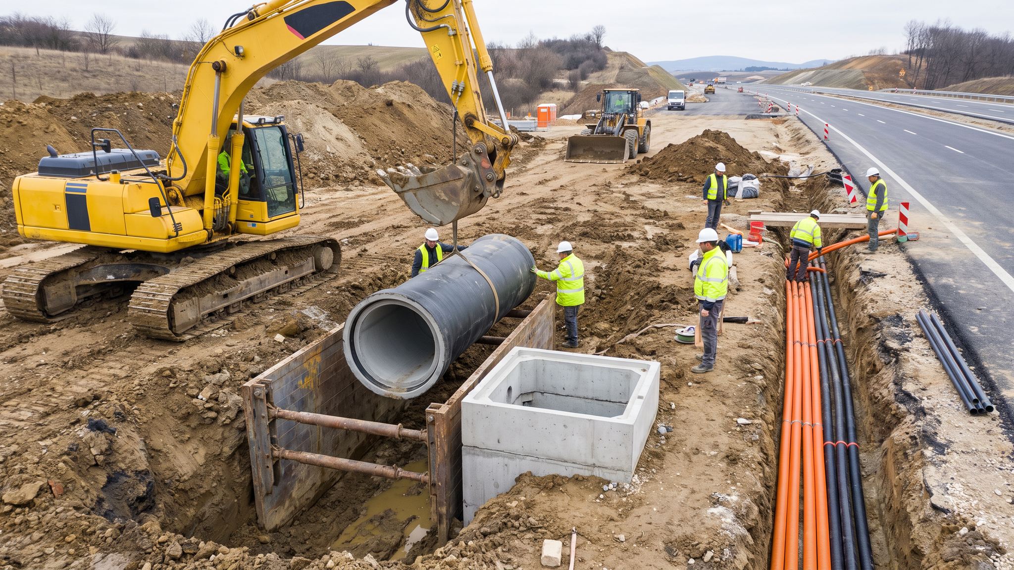
Drainage & Utility Corridors
Pipes, ducts, chambers and culverts - the buried networks installed before the pavement goes over them.
Open processCanonical guide: Roads & Highways
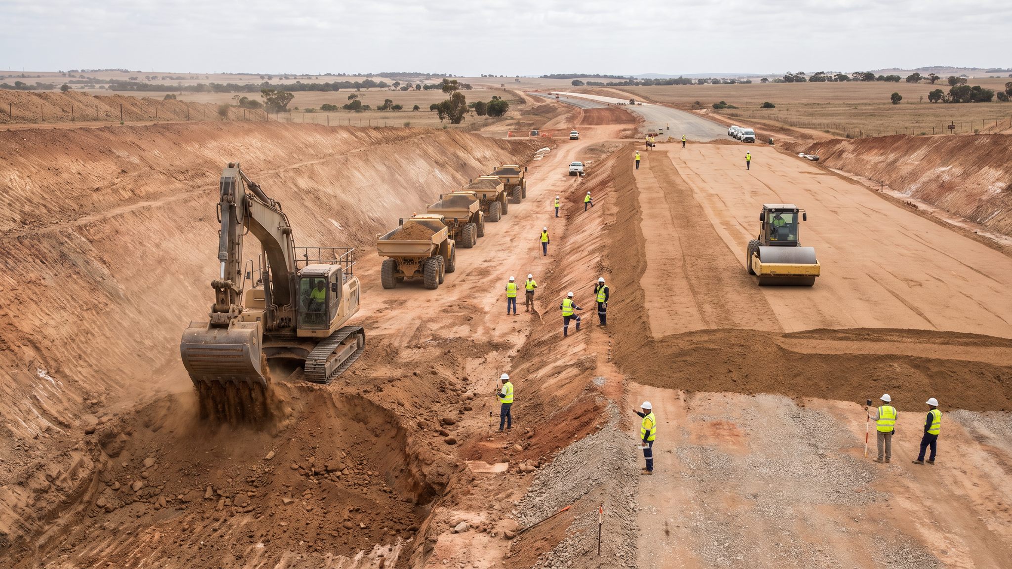
Bulk Earthworks - Cuttings & Embankments
Moving hundreds of thousands of cubic metres to build the corridor's shape - cuttings, embankments and the formation everything sits on.
Open processCanonical guide: Roads & Highways
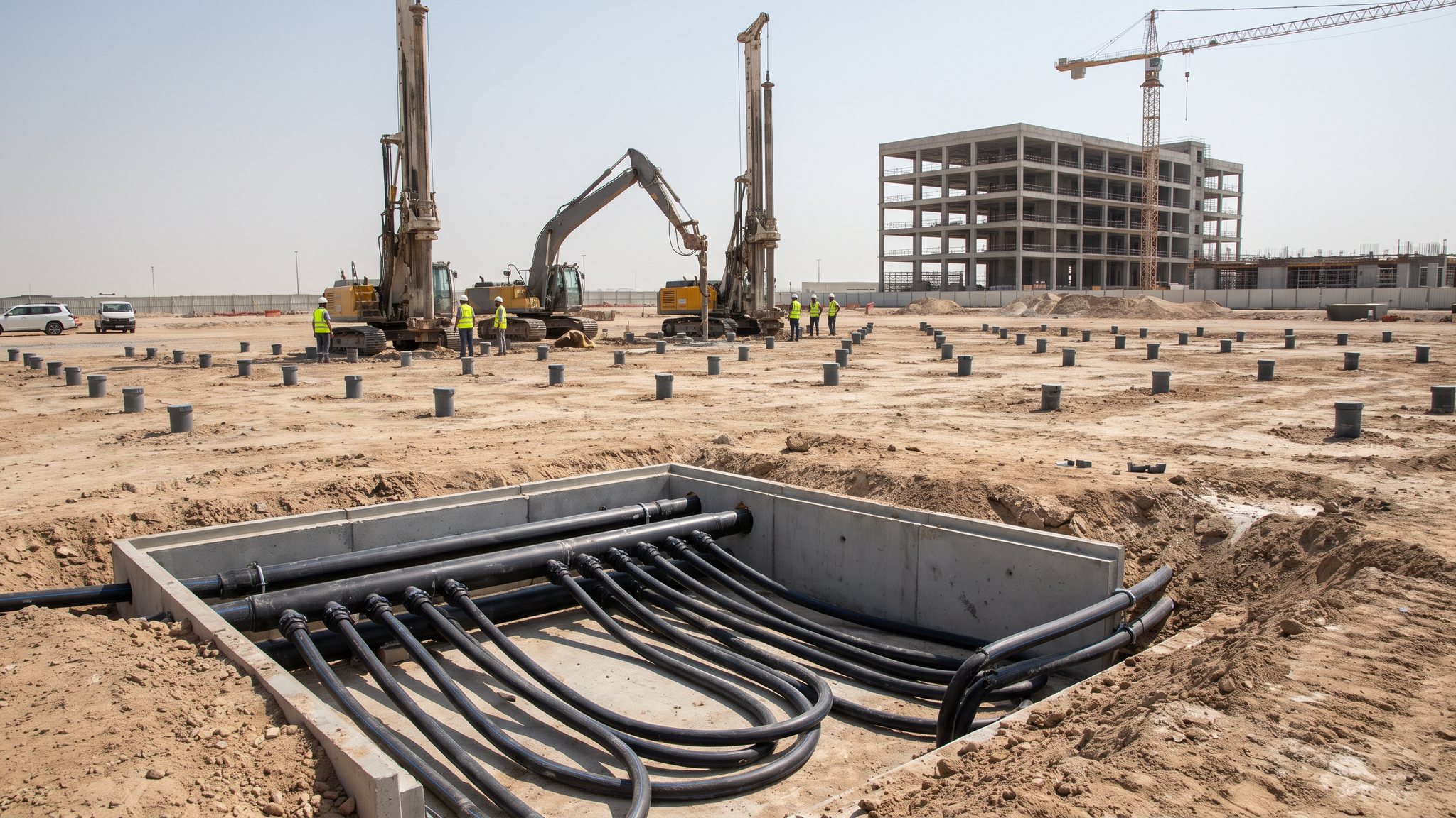
Shallow Geothermal - Commercial & District Schemes
Borehole fields under car parks, loops cast into foundation piles and shared ambient-loop networks - shallow geothermal at commercial and district scale, where thermal balance and drilling logistics rule.
Open processCanonical guide: Power Generation
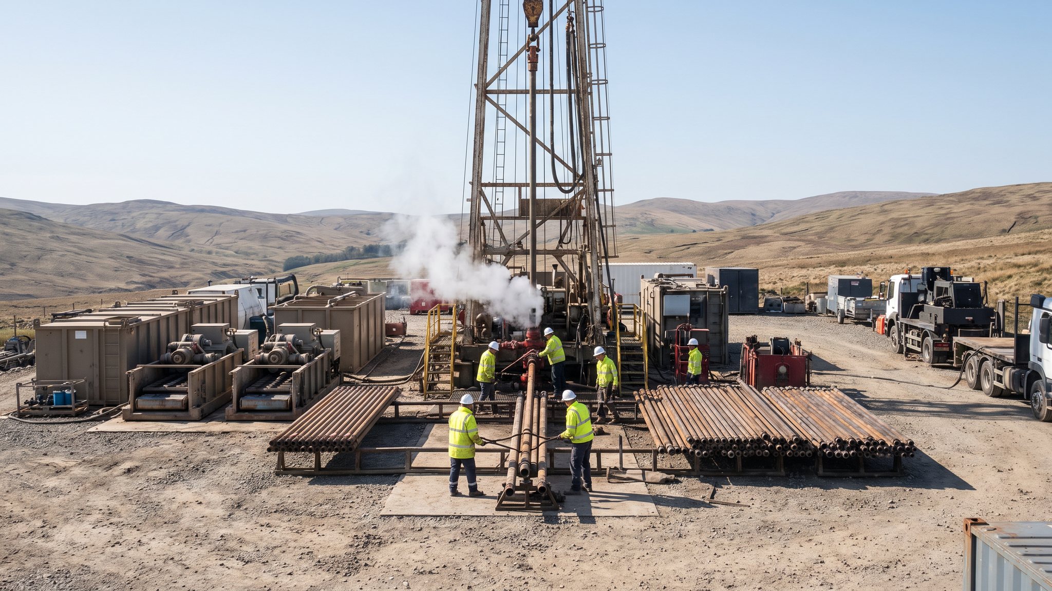
Deep Geothermal Drilling & Wells
Wells one to five kilometres deep drilled to oil-and-gas standards - casing strings, cement, mud logging and well control - the heavy end of the geothermal stream.
Open processCanonical guide: Power Generation

Concrete Frame Construction
Columns, walls and slabs cast in situ - the ribcage of a residential tower.
Open processCanonical guide: Residential & Housing
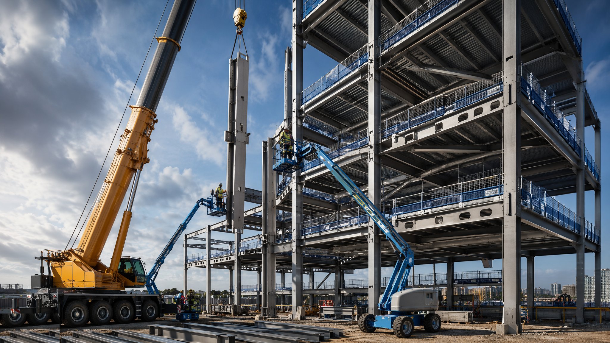
Steel Frame Construction
Fabricated off-site, erected at speed - bolted skeletons for frames that fly up.
Open processCanonical guide: Residential & Housing
District Energy & Utility Networks in depth
About District Energy & Utility Networks
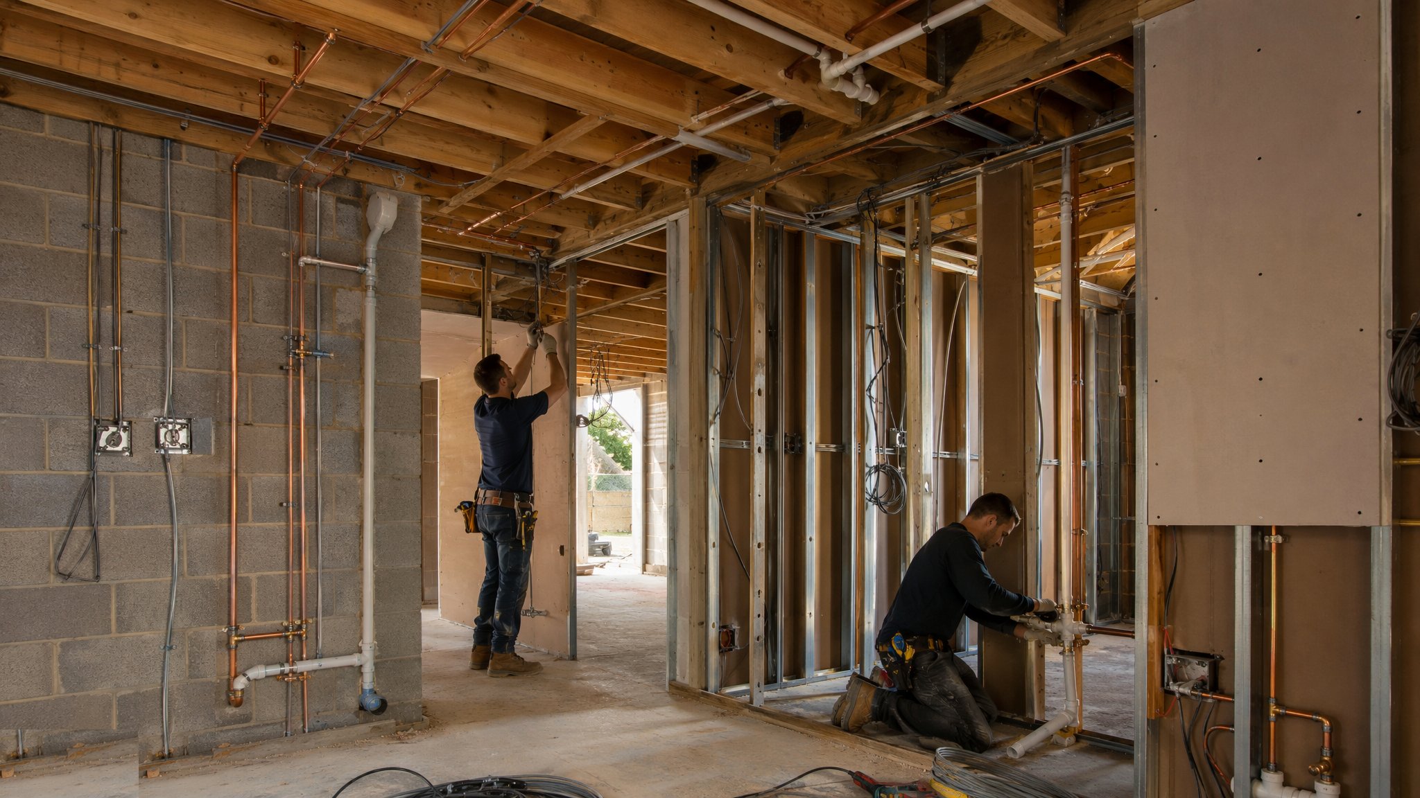
The three guides in this sector cover district heating and cooling networks - welded, insulated pipe systems with expansion to manage and leakage to find before backfill; energy centre construction, where the plant room is the product; and utility diversions and connections, the unglamorous work of moving everyone else's pipes and cables out of the way and tying new services into live networks.
District cooling: the UAE's defining utility
In the Gulf, district cooling is not an alternative technology; it is the default for any scheme above a handful of buildings. Providers such as Empower and Tabreed build central chilled-water plants - thousands of refrigeration tonnes of electric or absorption chillers - and distribute chilled water at around 4 to 6 degrees through welded steel or pre-insulated pipe networks to energy transfer stations in each building. For the construction sector this creates a whole asset class: the plant building itself, which is a process plant with a builder's envelope; the buried network, which is pipeline work with expansion and insulation as the critical details; and the transfer stations, which are plate heat exchangers, pumps and controls in a room the building developer provides. Connection capacity is booked early and shapes masterplan phasing.
The interface discipline runs both ways. The cooling provider specifies the transfer station and meters the energy; the building's MEP design is sized against the contracted capacity, and exceeding it has commercial consequences. On site, the network tie-in to a new building is a utility connection like any other - utility permit, witness points, pressure test, flush, chemical cleaning and passivation of the new pipework before it is allowed onto the live network - because debris from a new branch will foul heat exchangers across the district if it gets through.
Thermal energy storage is increasingly part of the plant: stratified chilled-water tanks that let the chillers run at night on cheaper power and discharge through the afternoon peak. Constructing one is water-sector work - a steel or concrete tank of tens of thousands of cubic metres with a diffuser system at its heart - and the watertightness and commissioning regime is closer to a service reservoir than to building services.
Heat networks and the UK picture
UK district energy is heat-led and policy-driven: heat networks are a stated decarbonisation route, with government funding schemes and forthcoming regulation pulling city-centre schemes forward. The construction content is pre-insulated bonded pipe systems - steel service pipe, polyurethane foam, polyethylene casing, with factory-made joints and, on the better systems, an alarm wire for leak detection - laid in city streets as a fourth utility alongside power, water and telecoms. Welding is to pressure-pipeline standards with radiographic or ultrasonic testing of welds, because a buried welded steel network carrying water at 90 degrees and up to 16 or 25 bar is a pressure system, and the industry learned from early failures that plumbing standards are not enough.
The chronic UK failure is water ingress at field joints: once the insulation gets wet the steel corrodes under the foam, invisibly, until the pipe fails years early. This is why jointing is done by certified installers, every joint is logged and tested, alarm wires are checked end to end before backfill, and the pressure test - typically 1.5 times design pressure held and logged - is a witnessed hold point nobody is allowed to waive. The energy centre end of the scheme is an industrial MEP package: boilers, combined heat and power engines or heat pumps, thermal stores, hydraulics and controls, commissioned as a process plant against flow and temperature performance, not as a building services fit-out.
Diversions and connections: the unglamorous core
Every corridor scheme in both markets starts with other people's pipes. Utility diversions - moving existing power, water, telecoms and cooling services out of the way of new works - are a sector of their own in practice: each asset belongs to a different utility with its own standards, inspectorate and permit regime, and each diversion is a mini-project with a design approval, a shutdown or live-working method, and a handback to the owning utility. The programme risk concentrates here because you cannot start the new corridor until the old services are moved, and the utility's own outage or shutdown windows are outside the main contractor's control. Experienced planners start diversion applications at tender stage.
Connections into live networks close the loop. Whether it is a chilled-water branch onto a live Empower main, a heat network extension onto a running system, or a multi-utility corridor being energised utility by utility, the tie-in is always the same shape: build and test the new work dead, book the window, manage the existing service - by-pass, isolate or drain down - make the joint, prove it, and hand back. The permit and witness regime from the owning utility governs every step, and the method statement is agreed with them before work starts, not submitted for interest.
Diversion work carries a documentation burden out of proportion to its size. Every moved service needs its before-and-after survey, its test certificates and its adoption or handback paperwork with the owning utility, and the main contractor holds the coordination risk between half a dozen organisations who do not talk to each other. A single unrecorded diversion is a utility strike waiting for the next scheme on the corridor.
From corridor access to energised network
The process chain across this sector is the corridor chain with a thermal twist: access and enabling works, survey and service location with trial holes to prove every crossing, excavation and bedding, pipe laying with welding and joint records, expansion provisions - loops, bellows or calculated natural flexibility, because a welded steel network that heats and cools wants to move and will find the weak point if the design has not allowed for it - then test, flush, insulate the field joints, backfill in controlled layers, reinstate, and finally connect and commission. Multi-utility corridors stack this sequence vertically with separation distances each utility specifies.
Commissioning a network is hydraulic and thermal: fill, vent, pressurise, flush to a cleanliness standard, chemically clean and passivate where specified, then bring the temperature up in controlled steps while expansion is monitored at the anchors and guides. The energy centre is commissioned against network demand, often with temporary loads before the first buildings connect. Handover packs carry the weld log, the joint log, the test certificates and the as-laid survey with coordinates and depths, because the network's whole life depends on the next contractor knowing exactly where it is.
Ground-source and ambient-loop schemes add a drilling and collector dimension: borehole fields drilled and grouted under the car parks and landscaping, headered in buried chambers, and pressure-tested loop by loop before the building ever rises. The sequencing constraint is absolute - the boreholes go in before the structure above them - which puts the energy contractor on site in the enabling-works phase, years before the plant room is fitted out.
The energy centre itself is the one place in the sector where the building and the process are inseparable. The structure is designed around the plant - craneage and knock-out panels for chiller replacement, slabs rated for vessels and thermal stores, acoustic treatment because the centre sits among the buildings it serves - and the MEP installation is industrial-grade: welded steel headers, large-bore valves, pumps in duty and standby pairs, and a control system that runs the whole district. Fit-out and commissioning overlap deliberately, because the first buildings on the network are usually waiting for cooling or heat before the centre is fully complete.
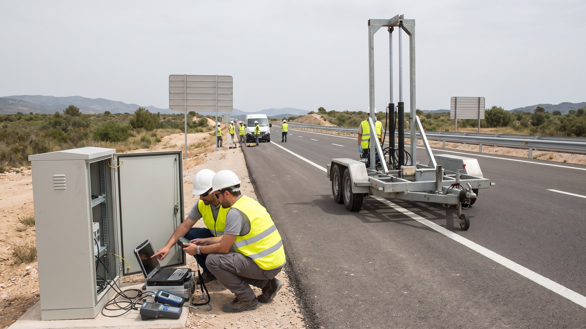
Metering is the commercial spine of the whole sector and is built in from the start: heat and cooling meters at every transfer station, temperature and flow instrumentation on the network, and a billing data chain from sensor to invoice. On site this means instrument installation, calibration certificates and communications testing are part of the MEP scope, not an operator afterthought, and a transfer station that cools the building but cannot meter it fails its handover as surely as one that leaks.