Horizontal directional drilling
A steered bore driven under the obstacle rather than a trench cut through it - the road, the river or the railway never knows you were there.
Last updated 2026-09-05
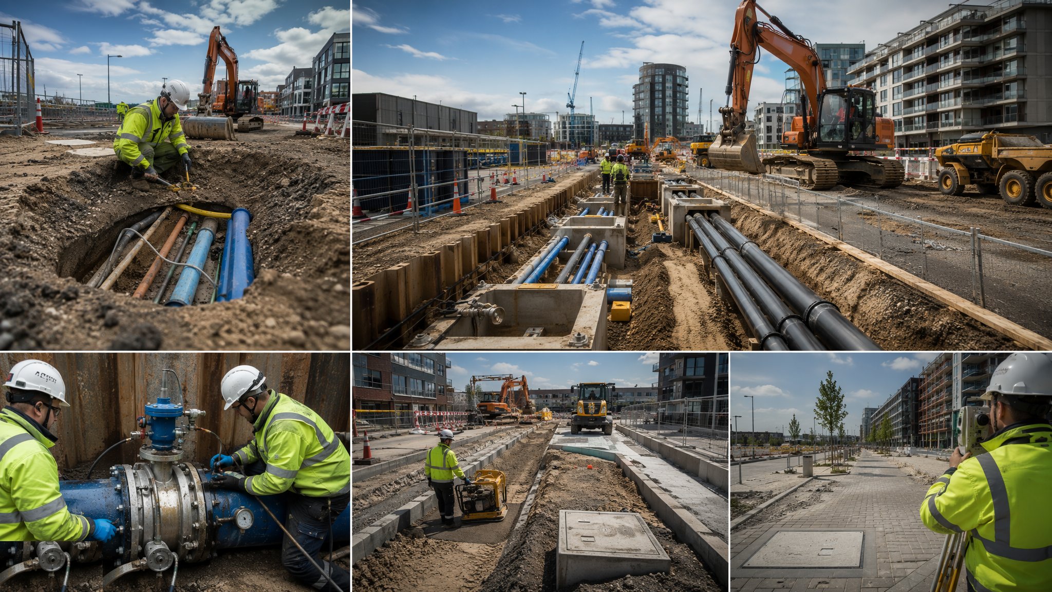
What is Horizontal directional drilling?
Horizontal directional drilling installs a pipe or duct along a curved path beneath the ground without opening a trench along its length. A rig sits in a compound at one end, pushes a steerable drill string into the ground at a shallow entry angle, drives it in an arc under whatever is in the way, and brings it back to the surface at a receiving pit on the far side. The bore is then opened up to the size the product pipe needs and the pipe is pulled back through it. Two small compounds and two small pits replace a trench that might otherwise have run for hundreds of metres. On most projects that is the whole argument for the method - the ground surface between the entry and exit points is never touched.
The work runs in three recognised stages. The pilot bore establishes the line and level, steered by a drill head that can be turned as it is pushed and tracked from the surface or from within the bore so the crew always know where it is. Reaming follows: a cutting head is pulled back and forth through the pilot bore to enlarge it, in one pass or several depending on the finished size, so that the hole is comfortably larger than the pipe going into it. Pullback is the last stage, with the product pipe - commonly a welded polyethylene string laid out and jointed in one length before the pull starts - drawn back through the reamed bore in a single continuous operation. Once a pullback begins it is not stopped, because a string left standing in a bore can grip.
Drilling fluid is doing most of the quiet work throughout. It carries the cuttings back out of the bore, cools and lubricates the head and the string, and helps hold the bore open in ground that would otherwise close on it. That same fluid is the source of the technique's signature failure, frac-out, where fluid under pressure finds a path to the surface or into a watercourse instead of returning down the annulus, and breaks out in the middle of a field, a carriageway or a river. Frac-out is a ground and route problem before it is a drilling problem, which is why the route is investigated, the depth of cover is set by the designer, and existing buried services are proven on the ground before the rig arrives. Directional drilling competes with open-cut trenching, and it wins where the surface is the expensive part: live carriageways, railways, rivers and canals, contaminated ground, mature trees and anywhere a road closure is worse than a specialist crew. It loses in ground it cannot hold or steer through - open gravels and cobbles, boulder-strewn glacial deposits and running sand can defeat a bore that would have been a straightforward day's trenching.
How does Horizontal directional drilling work, step by step?
- 1
Step 1: Prove the route before anything is drilled
The route is desk-studied, surveyed and then physically proven. Existing utility records are obtained and treated as a starting point rather than as fact, the line is scanned with detection equipment, and trial holes are dug at the crossings and anywhere the records are doubtful. A ground investigation along the line tells the designer whether the bore can be held open and steered at all, and where the water table sits. The designer then sets the entry and exit positions, the entry angle, the profile of the bore and the depth of cover, and the specialist contractor confirms the rig and the fluid system can achieve it. Consents follow the same line: a crossing under a road, a railway, a river or a canal belongs to the body that owns it, and their conditions are agreed before the compound is set out.
- 2
Step 2: Set up the compounds and the fluid system
The rig compound needs firm level ground, room to handle drill rods, and space for the fluid tanks, mixing plant and cuttings containment. Entry and exit pits are excavated and supported, and both are treated as excavations in their own right rather than as an afterthought at the end of a drilling job. The receiving compound needs enough clear length to lay out and joint the product pipe in one string, which on a long crossing is often the constraint that decides where the exit goes. Fluid returns are contained, screened and recirculated where possible, and the residue is disposed of as a waste stream rather than run to a ditch.
- 3
Step 3: Drive and steer the pilot bore
The pilot bore is pushed and rotated in rod lengths, with the drill head steered by orienting an asymmetric face and pushing without rotation to turn, then rotating to run straight. Position is tracked continuously - commonly by a walkover locator following a transmitter in the head, or by a wireline or gyroscopic system where the surface above cannot be walked - and the recorded position is compared against the design profile as every rod goes in. Small corrections early are cheap. A bore allowed to drift and then hauled back onto line puts a kink in the path that the reamer and the pullback will both find later.
- 4
Step 4: Ream the bore to size
Once the pilot bore surfaces at the exit, the drill head is swapped for a reamer and the bore is enlarged by pulling the cutting head back towards the rig while fluid clears the cuttings. Large bores are opened in successive passes rather than in one, and the finished bore is made comfortably larger than the outside diameter of the product pipe so that the pipe can be drawn through without binding. The reamer type follows the ground - cutting, mixing or compacting - and that selection belongs to the specialist contractor, who is also the party watching the fluid returns pass by pass for the first sign that the bore is not behaving.
- 5
Step 5: Pull back the product pipe
The product pipe is jointed into a single string, pressure tested where the specification calls for it, and connected to the drill string through a swivel so that the rotating reamer does not spin the pipe. The pull is then run as one continuous operation, with the string supported on rollers or in a trench so it enters the bore on a gentle curve rather than being dragged over the ground. Pulling loads are monitored throughout, and a rising load is a signal to stop and think rather than to pull harder. Where the design requires it the annulus is grouted after the pull.
- 6
Step 6: Test, record and reinstate
The installed pipe or duct is proved to the specification - pressure tested, mandrel tested or proved with a duct rod, depending on what it is - and the as-built line and level of the bore are recorded from the tracking data and issued as a record for the asset owner. Entry and exit pits are backfilled and reinstated, the compounds are stripped, and the fluid residues and cuttings leave site as controlled waste. On a crossing under a third party's asset, the owner's own sign-off is part of the completion, not a formality afterwards.
What are the benefits of Horizontal directional drilling?
- The ground between entry and exit is never opened, so roads, railways, rivers and mature landscape stay in service
- Avoids the traffic management, diversions and public disruption that a long open-cut trench brings
- Reduces excavated arisings and imported backfill compared with trenching the same length
- Keeps the works away from contaminated ground rather than digging it up and having to dispose of it
- Curved profiles let the line pass under obstacles that a straight thrust could not clear
- Often the only realistic option where a crossing owner will not permit a surface opening at all
What are the limitations of Horizontal directional drilling?
- Ground governs everything - open gravels, cobbles, boulders and running sand can stop a bore that a trench would have handled easily
- Frac-out risk, with drilling fluid breaking out at the surface or into a watercourse, has to be assessed and managed on every crossing
- Undetected existing services on the line are a serious strike risk, and detection alone is not proof
- Needs compound space at both ends, plus a clear run to lay out the product pipe in one string
- Generates drilling fluid and cuttings that have to be contained, treated and disposed of
- Specialist plant and crews cost more per day than a trenching gang, so short runs rarely justify it
What is Horizontal directional drilling best suited for?
What plant does Horizontal directional drilling need?
- Directional drilling rig with drill rods, steerable heads and reamers, sized to the crossing
- Drilling fluid mixing and pumping plant, with tanks, screening and recirculation gear
- Tracking equipment - walkover locator, or wireline or gyroscopic system where the surface cannot be walked
- Excavator and support equipment for entry and exit pits, plus pit shoring
- Pipe handling and fusion jointing plant for the product string, with rollers for the pull
- Utility detection and vacuum excavation equipment for proving existing services
How is Horizontal directional drilling quality-checked?
- Utility records obtained, the line scanned and trial holes dug before drilling starts
- Crossing consents and the asset owner's conditions in place before the compound is set out
- Recorded bore position compared against the design profile at every rod, with deviations reported to the designer
- Drilling fluid returns monitored continuously, with a written frac-out response plan agreed before the bore begins
- Pullback loads recorded, and a rising load treated as a stop-and-review point
- Product pipe proved after installation and the as-built bore profile issued to the asset owner
Back to process
Utility Diversions & Connections