Rainscreen and over-cladding zones
A drained and ventilated outer skin over a separate weather line - and a cavity that must be closed by design.
Last updated 2026-09-05
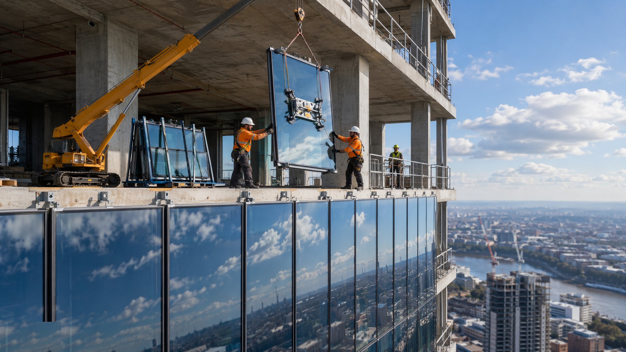
What is Rainscreen and over-cladding zones?
A rainscreen is not a waterproof wall. It is an outer skin that takes the weather off the building, behind which a ventilated cavity and a separate, continuous weather line do the actual job of keeping water out. Rain that gets past the open or sealed joints between the outer panels runs down the back of the panel or the face of the cavity and drains away, while air moving through the cavity dries the construction and helps equalise pressure so that less water is driven inwards in the first place. Over-cladding is the same principle applied to an existing building: a new outer skin, insulation and support system installed over the existing wall to improve appearance, weathering and thermal performance without rebuilding it.
The system has four distinct layers and each has to be right. Innermost is the backing wall and, over it, the continuous air and weather barrier that is the real weather line. Then insulation, held tight to the backing wall with no gaps, because a gap in insulation is a cold bridge and a route for air. Then the ventilated cavity, which must be kept clear and open so it can drain and breathe. Then the support system - brackets through the insulation into the backing wall, carrying rails that the panels hang from - and the panels themselves. The support system is the structural element and it is engineered for the loads the facade engineer sets, with thermal isolation at the bracket so the whole assembly is not short-circuited by a grid of metal.
The cavity is also the reason rainscreen work carries the scrutiny it does. A continuous open void behind cladding is a ready-made route for fire and smoke to travel vertically and horizontally behind the outer skin, invisibly, past compartment lines. Cavity barriers are therefore designed into the assembly at the positions the fire strategy requires - around openings, at compartment boundaries, at edges and terminations - and their installation is inspected and recorded before the panels close the cavity, because after that nobody can see them. Materials, the build-up and the barrier arrangement are all matters for the designers and the fire engineer on a project-specific basis, and site substitution of any component in a rainscreen build-up is never a site decision.
How does Rainscreen and over-cladding zones work, step by step?
- 1
Step 1: Establish the build-up with the designers
The architect, the facade engineer and the fire engineer settle the full build-up: backing wall, air and weather barrier, insulation, cavity, support system, cavity barrier arrangement and panel type. Every layer is specified as part of a coordinated assembly rather than picked separately, and materials, junctions and terminations all follow from the fire and weathering strategy for that particular building. On over-cladding work the condition of the existing wall is investigated first, because the new system has to be supported by and fixed back to something known.
- 2
Step 2: Survey the backing wall and prove the fixings
The backing wall is surveyed for line, level, plumb and condition, and on existing buildings for whatever it is actually made of behind the finish. Bracket positions are set out from that survey, and pull-out testing of trial anchors into the actual substrate is normal practice before the support system is procured, because a bracket is only as good as what it is fixed into. Deviations in the backing wall are taken up in the bracket adjustment, and if the deviation exceeds what the system can absorb the designer decides the remedy.
- 3
Step 3: Install the air and weather barrier continuously
The barrier over the backing wall is the real weather line, so it is installed continuously, lapped in the right direction, and sealed at every penetration, junction, opening reveal, floor edge and termination. Details around windows, brackets, service penetrations and abutments are where barriers fail, and they are installed to drawn details rather than improvised. The barrier is inspected while it is visible and photographed as a record, because the insulation and cladding that follow make it permanently inaccessible.
- 4
Step 4: Fix brackets and insulate without gaps
Brackets are fixed through to the backing wall at the engineered positions and fixings, with thermal isolation at the interface where the design requires it. Insulation is then installed tight to the backing wall and tight between boards, cut neatly around brackets rather than forced or left short, and fixed at the specified pattern. Gaps, compressed boards and loose fitting are the common defects and they cost both thermal performance and air tightness. Any penetration made through the insulation is sealed back to the barrier.
- 5
Step 5: Install cavity barriers and keep the cavity clear
Cavity barriers are installed at the positions the fire strategy requires - typically at compartment lines, around openings and at the edges and terminations of the cladding zone - fitted tight and continuous with correctly formed junctions and correct orientation, and installed by people trained in that specific product. This is the single most important inspection point in the whole assembly, because once the panels go on nothing can be seen. Each barrier is inspected, photographed and recorded against its position before it is covered. The ventilated cavity elsewhere is kept clear and free of debris, offcuts and squeezed insulation so it drains and ventilates as designed.
- 6
Step 6: Erect the rails and hang the panels
Carrier rails are fixed to the brackets and aligned to give a true, plumb plane for the panels, with the movement provision the system requires at the joints and splices. Panels are then hung, hooked or fixed to the rails in the sequence and with the fixings the system specifies, working from a fixed datum so joint lines stay consistent across the elevation. Open joints are set out to the designed width and the drainage path behind them is kept clear. Handling large panels at height is wind-sensitive work with a lifting plan and a wind limit.
- 7
Step 7: Complete terminations, test and record
Copings, flashings, sills, reveals, base details, corners and every junction with another system are completed to the approved details, because a rainscreen fails at its edges far more often than in its field. Water testing on a sample of the assembly during installation is normal, along with air tightness testing where the specification calls for it. The record package - barrier photographs, cavity barrier positions and inspection sign-offs, fixing and pull-out test results, panel and material traceability - is compiled as the work proceeds and handed over, because it is the only evidence that the concealed layers were built as designed.
What are the benefits of Rainscreen and over-cladding zones?
- Drained and ventilated construction handles wind-driven rain better than a single sealed outer line
- The weather line and the appearance line are separated, so each can be optimised independently
- Continuous external insulation improves thermal performance and reduces cold bridging
- Ventilation dries the construction, which helps the durability of the backing wall
- Over-cladding upgrades an existing building without rebuilding the wall or vacating it entirely
- Wide choice of panel materials, sizes and joint treatments for the architecture
What are the limitations of Rainscreen and over-cladding zones?
- The cavity is a fire route and must be closed by designed cavity barriers, correctly installed and recorded
- Nearly all of the important work is concealed, so inspection has to happen before the panels close it
- Performance depends on the continuity of the air and weather barrier, which is easy to compromise at junctions
- Bracket fixings into an unknown or poor backing wall need investigation and testing before procurement
- A cold bridge grid can undo the insulation if bracket thermal isolation is not designed and installed
- Materials and build-ups are project-specific and site substitution is never acceptable
What is Rainscreen and over-cladding zones best suited for?
What plant does Rainscreen and over-cladding zones need?
- External access - scaffold, mast climbers or cradles - designed, erected and inspected
- Survey instruments for backing wall survey, bracket setting-out and panel datum lines
- Drilling and anchor fixing equipment with calibrated torque tools and pull-out test rigs
- Hoists, mini cranes or panel lifters for handling large cladding panels at height
- Cutting and edge-finishing equipment with dust extraction for panel materials
- Water and air tightness testing equipment, and cameras for the concealed-works record
How is Rainscreen and over-cladding zones quality-checked?
- Backing wall surveyed and anchor pull-out testing carried out in the actual substrate before procurement
- Air and weather barrier inspected for continuity, laps and sealing at every junction, and photographed before covering
- Insulation checked for tight fit, no gaps, correct cutting around brackets and correct fixing pattern
- Cavity barriers inspected, photographed and recorded against position, continuity and orientation before panels close the cavity
- Cavity confirmed clear of debris and obstruction, with drainage and ventilation paths open
- Panel alignment, joint widths and terminations checked, with sample water testing and a full concealed-works record handed over