Monopiles with transition pieces
One very large steel tube driven into the seabed, with a transition piece on top carrying everything the crew touches.
Last updated 2026-09-07
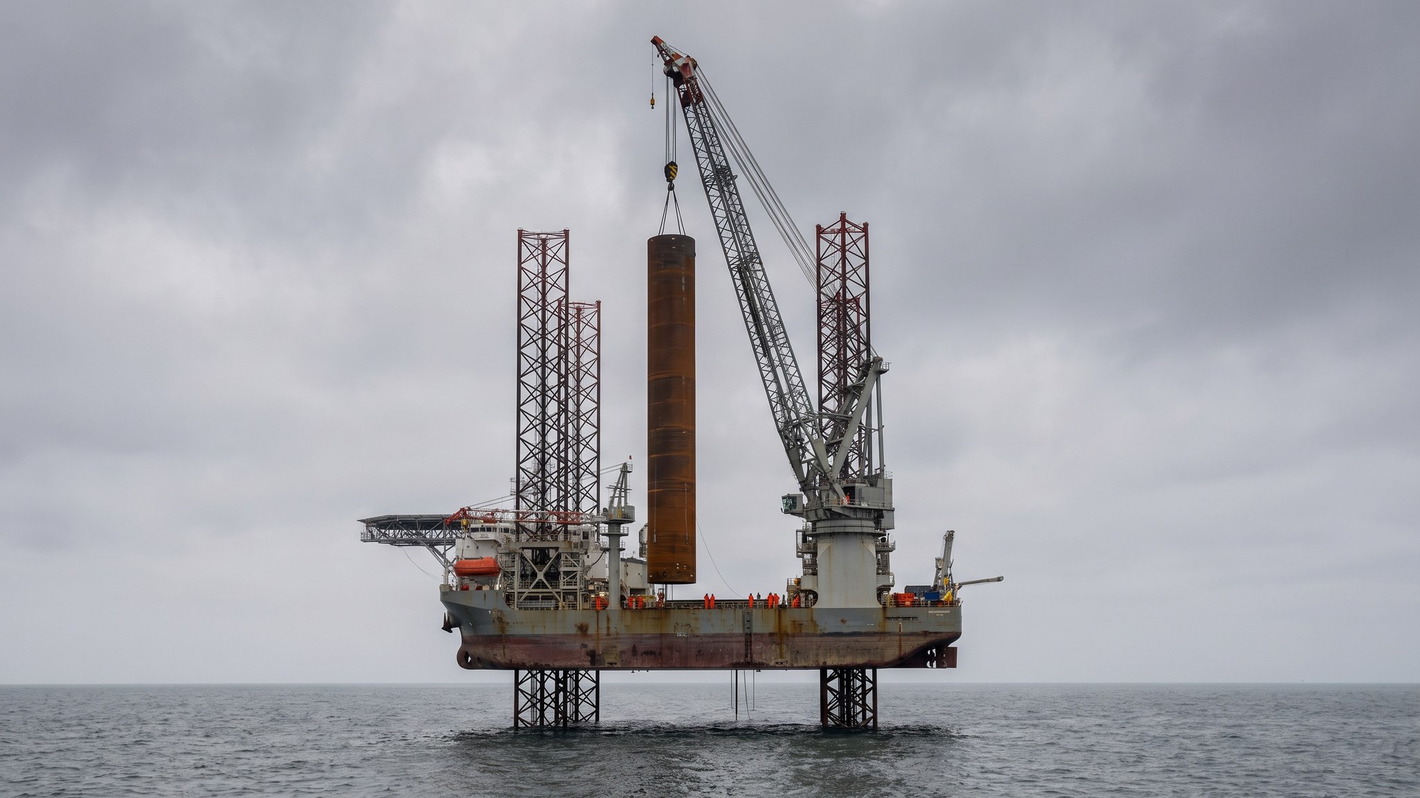
What is Monopiles with transition pieces?
A monopile is the simplest offshore foundation there is: a single rolled and welded steel tube driven into the seabed until it is fixed enough to hold a turbine steady for twenty-five years or more. Modern monopiles for commercial projects are commonly 7-10 m in diameter and weigh well over a thousand tonnes, and the largest sit above that. The tube is not uniform. It is fabricated from cans of varying wall thickness, thicker where the bending moment is highest and thinner where it is not, and the designer decides that distribution from the loads, the ground and the fatigue life the specification demands. On top sits the transition piece, a shorter section that corrects any lean in the driven pile and carries the boat landing, the ladder, the external and internal platforms, the cable entry, the anodes and the J-tube that guides the array cable in.
Monopiles became the workhorse of the industry because they industrialise well. Every unit on a project is broadly the same object, fabricated on a production line, rolled out of a yard onto a quay and shipped in batches. The installation sequence is short and repeatable: upend the pile, hold it in a gripper, drive it, check verticality, install the transition piece, then move on. On a settled project a well-drilled marine spread can install a foundation in a day and sometimes better, which is what makes the economics of large arrays work at all. Water depth is the boundary. Monopiles are the natural answer in shallower water, and as depth increases the pile has to grow disproportionately to resist the overturning moment until the steel weight and the driving effort stop making sense against a lattice.
The constraint that shapes the whole operation is noise. Driving a very large tube into the seabed puts a great deal of sound energy into the water column, and underwater noise is harmful to marine mammals. Every project therefore plans around mitigation: soft-start procedures that begin driving gently so animals can move away, marine mammal observers and acoustic monitoring before and during driving, seasonal restrictions in sensitive periods, and noise abatement systems such as bubble curtains or sleeves deployed around the pile. Those measures are consent conditions, not optional extras, and they cost time on every single pile. The other constraint is the weather. Upending and gripping a thousand-tonne tube in open water is only done inside a defined window, and the installation contractor plans each operation against a forecast with limits the project has agreed in advance.
How does Monopiles with transition pieces work, step by step?
- 1
Step 1: Fix the ground model and size the pile
Everything starts with the site investigation. Boreholes and cone testing at or close to every foundation position build a ground model across the array, because seabed conditions vary from one position to the next and a single design applied everywhere is either wasteful or unsafe. The designer combines that model with the turbine loads, the water depth, the wave and current climate and the required fatigue life, then sets the diameter, the wall thickness distribution and the embedment for each position. Positions are often grouped into a handful of design families so that fabrication stays repeatable. The output is a pile schedule that tells the yard what to build and the installation contractor what to expect at each location.
- 2
Step 2: Fabricate, coat and load out
Plate is rolled into cans, the cans are welded into sections and the sections are welded into a complete pile, with the circumferential welds inspected throughout because they carry the fatigue duty. External coatings and anodes go on for corrosion protection, internal secondary steelwork is fitted, and the pile is marked up so the crew offshore can read penetration from the deck. Transition pieces are outfitted separately and arrive far more complete than the piles, with platforms, ladders, boat landing and internal fit-out already installed. Load-out from the fabrication yard onto the transport barge or the installation vessel is itself an engineered operation, and quay strength, crane reach and sea fastening all govern how many units go out per trip.
- 3
Step 3: Prepare the position and set the spread
Before the vessel arrives the position is surveyed and cleared. Unexploded ordnance survey and clearance, boulder clearance and a check for wrecks and archaeology all happen ahead of the installation campaign, and any obstruction found is dealt with rather than driven through. The installation vessel arrives on position, jacks up or holds station on dynamic positioning depending on its type, and the crew set out the gripper frame that will hold the pile vertical. Scour protection, usually a graded rock layer, is placed either before or after the pile depending on the design, and that choice belongs to the designer.
- 4
Step 4: Upend, stab and grip the pile
The pile is lifted from its cradle horizontally, upended to vertical using the main crane and an upending arrangement, and lowered through the gripper frame until its toe reaches the seabed. In most ground the pile self-penetrates several metres under its own very considerable weight before any driving starts. Verticality is monitored continuously while the gripper holds the pile, because a lean corrected early is trivial and a lean discovered late is not. Heavy offshore lifts of this scale are planned by the installation contractor and independently reviewed before the campaign starts.
- 5
Step 5: Drive to the design penetration with noise mitigation running
The hammer is placed on the pile head and driving begins with a soft-start sequence at reduced energy, so that any marine mammals in the area move off before full energy is applied. Noise abatement is deployed and confirmed working before that point. Driving then proceeds in a controlled sequence while blow counts and penetration are logged continuously, giving a driving record that is compared against what the ground model predicted. Where the record departs from expectation the contractor stops and the designer assesses it. Refusal on an unexpected hard layer, or unexpectedly easy driving, are both engineering events rather than production problems.
- 6
Step 6: Install the transition piece and make the connection
With the pile driven, the transition piece is lifted on and set over or into the pile head. Any lean left in the driven pile is corrected here, and the transition piece is held and adjusted until it is vertical within the tolerance the specification sets. The connection between the two is then made permanent. Grouted connections, bolted flange connections and combinations of the two are all used, and the choice is the designer's and is made long before the vessel sails. Whatever the arrangement, the connection is a controlled operation with its own procedure, its own hold points and its own records.
- 7
Step 7: Complete the outfitting and hand over the interface
The secondary steelwork is checked and completed, corrosion protection is confirmed, the internal platforms and access arrangements are made safe, and the J-tube and cable entry are made ready for the array cable that will follow in a separate campaign. Navigation aids and lighting are commissioned. The foundation is then surveyed as-built, and the position, orientation, level and flange condition are recorded because the turbine that lands on it later has to arrive at a known interface. That handover pack is what the turbine installation contractor works to.
- 8
Step 8: Survey, monitor and close out
After installation the seabed around the foundation is surveyed to confirm the scour protection is where it should be, and repeat surveys through the life of the project track whether it is moving. Structural monitoring instruments fitted on a sample of foundations give the designer real behaviour to compare against the assumptions. The driving records, the as-built survey, the connection records and the inspection reports are assembled into the foundation file for that position. On a large array this happens dozens or hundreds of times, and the discipline of the paperwork is what keeps the campaign repeatable rather than heroic.
What are the benefits of Monopiles with transition pieces?
- The simplest offshore foundation to fabricate, with a single repeated object suiting production-line manufacture
- Shortest offshore installation sequence of the fixed options, commonly around a day per foundation on a settled campaign
- Mature supply chain and a large pool of experienced installation contractors and vessels
- The transition piece arrives heavily pre-outfitted, moving work from open water into the fabrication yard
- No seabed preparation or levelling needed in most ground, unlike a gravity base
- Well understood by designers, insurers and lenders, which lowers the commercial risk of a large array
What are the limitations of Monopiles with transition pieces?
- Driving noise is the dominant environmental constraint, and mitigation, monitoring and seasonal restrictions all cost programme time
- Steel weight grows disproportionately with water depth, so the option runs out as sites move deeper
- Boulders, rock horizons and other obstructions can stop a pile short and force drilling or a redesign at that position
- Very heavy single lifts need a large installation vessel, and those vessels are scarce and expensive
- The pile-to-transition-piece connection is a known fatigue-critical detail that demands careful design and controlled execution
- Decommissioning a driven pile is harder than recovering a structure that was never driven
What is Monopiles with transition pieces best suited for?
What plant does Monopiles with transition pieces need?
- Jack-up or floating heavy-lift installation vessel with a main crane sized for the pile and the transition piece
- Pile gripper frame and upending arrangement mounted on the vessel
- Hydraulic impact hammer with its power pack, spread and sea fastening
- Noise abatement equipment such as bubble curtain systems, with compressors and deployment gear
- Feeder barges and tugs where the installation vessel does not carry its own foundations
- Survey spread for position, verticality and as-built recording, plus remotely operated vehicles for seabed inspection
How is Monopiles with transition pieces quality-checked?
- Weld inspection through fabrication, with the fatigue-critical circumferential welds fully covered
- Coating and anode verification before load-out, with holiday testing of the external coating
- Continuous verticality monitoring while the pile is in the gripper, recorded against the tolerance in the specification
- Driving records logged blow by blow and reconciled against the ground model, with a stop and assess route when they diverge
- Noise monitoring and marine mammal observation records kept for every pile as consent evidence
- As-built survey of position, level, orientation and flange condition, issued as the interface handover for turbine installation
More offshore foundations methods
Next method
Jackets on pin piles or suction buckets