25 kV AC overhead line equipment
Wires carried above the track on masts and portals, collected by a pantograph on the roof of the train.
Last updated 2026-09-05
What is 25 kV AC overhead line equipment?
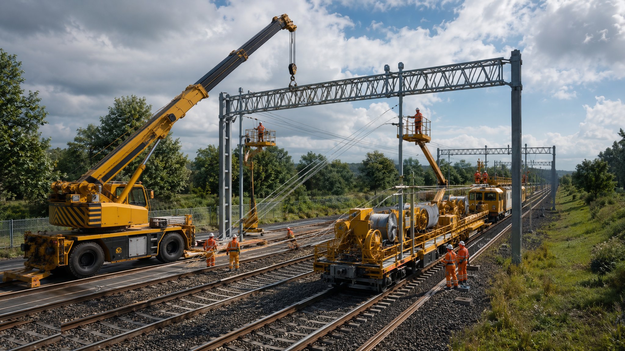
Overhead line equipment is the standard way main line railways are electrified. Current is delivered to the train through wires suspended above the track and collected by a pantograph on the vehicle roof. The arrangement is simple to describe and demanding to build. A contact wire runs along the centre line of the track and is held in position by a catenary above it, which is in turn carried by structures at intervals along the route. Those structures are masts on single lines and portals or headspans where several tracks have to be spanned at once. Feeder stations along the route take supply from the public network and pass it into the overhead system, and switching equipment allows the infrastructure manager to divide the route into sections that can be worked on independently. Everything the passenger sees is a wire. Almost all of the project is what holds it up.
The works divide into four streams that overlap through the programme. Foundations come first, because every structure needs one and the ground along a railway corridor is rarely uniform. Structures follow, erected in the corridor and often craned in from the track itself. Wiring runs are then pulled in and regulated. Finally the power supply, switching and control equipment is brought into use. Each stream has a different plant fleet, a different labour type and a different rate of progress, and the sequencing of the four across a live railway is the single hardest planning problem on an electrification project. On most projects the physical installation is not the constraint. Access is. Work happens in possessions granted by the infrastructure manager, commonly overnight or across weekends, and the productive time inside a possession after travel, setting up and handing back is a fraction of its nominal length.
Electrification also changes the railway permanently. A wire needs room above the train, and every bridge, tunnel, station canopy and footbridge along the route has to accommodate it. Where a structure does not, the options are to lower the track, to rebuild the structure or to alter the overhead arrangement locally, and each of those is a civil engineering project attached to what began as a wiring project. Route clearance work of this kind commonly costs and delays more than the overhead line itself, which is why the survey and clearance assessment is done early and taken seriously. Every aspect of the live system - isolation, earthing, permits and access to the equipment - sits under the infrastructure manager's regime and is carried out only by competent, qualified and authorised staff. Nothing about that regime is summarised here, and nothing in this overview should be read as a working instruction.
How does 25 kV AC overhead line equipment work, step by step?
- 1
Step 1: Survey the route and fix the clearance strategy
The route is surveyed in detail before anything is designed. The designer needs the position of every track, the shape of every overbridge, tunnel and canopy, the location of buried and lineside services, and the condition of the corridor itself. From that survey comes the clearance strategy: which structures accept the overhead system as they are, which need the track lowering beneath them, which need rebuilding and which need a local alteration to the overhead arrangement. On most projects this exercise sets the cost and the programme, because the civil works it identifies are far larger than the wiring. Doing it late is the classic way an electrification scheme loses control of its budget.
- 2
Step 2: Design the overhead system and the supply
The designer sets out where structures go, what each one carries and how the wiring is divided into lengths along the route. In parallel the electrical designer establishes where supply is taken from the public network, where feeder stations and switching sites are placed, and how the route is split into sections. The two designs are inseparable: the position of a switching site changes where wiring runs start and stop, and the position of a structure is constrained by what is buried beneath it. All the dimensional and electrical parameters belong to the specification and to the infrastructure manager, and are not repeated here.
- 3
Step 3: Install the foundations
Every structure needs a foundation, and there can be many hundreds of them along a route. Ground conditions vary along the corridor, so foundation types vary with them - piled, augered, mass concrete or a proprietary driven arrangement. The work is done from the track using road-rail plant, or from the lineside where access allows. The main risks are the ones common to any excavation in a railway corridor: buried services, unrecorded structures, contaminated ground and the stability of the embankment or cutting alongside. Trial holes and service location work precede the piling, not the other way round.
- 4
Step 4: Erect the structures
Masts, portals and headspans are set on the completed foundations, commonly craned in from a train or from road-rail plant working in a possession. Progress here is measured in structures per shift, and the number is usually small once travel, setting up and handing back are taken off the possession length. Registration and small steelwork that positions the wires relative to the track is fitted at this stage or shortly after. The work is planned so that each possession leaves the railway in a state that can be handed back and used, which usually means erecting structures well ahead of the wiring front.
- 5
Step 5: Run and regulate the wiring
Wiring trains pull the catenary and contact wire into place along each length and the wires are brought to their designed condition and position. Gear at the ends of each length allows the wires to expand and contract with temperature. The values, the settings and the sequence are the designer's and the infrastructure manager's, and are not given here. What is worth understanding is the pace: a wiring train occupies the whole possession, needs a clear and continuous run of track, and cannot work around other trades in the same section. Wiring is therefore planned as an exclusive activity, which makes it the hardest thing on the project to recover once it slips.
- 6
Step 6: Build the supply, switching and control equipment
Feeder stations, switching sites and their control and protection equipment are built alongside the lineside works, often on separate compounds with their own access and their own connection to the public network. This stream runs on a different clock to the wiring, because it depends on a third party energising a connection at a date the project does not control. Delay here strands finished overhead line that cannot be brought into use, so the connection programme is tracked from the first week of the project.
- 7
Step 7: Assure, energise and enter service
Before any part of the system carries current it goes through the infrastructure manager's assurance and acceptance process, carried out by competent and authorised staff under a documented regime. Energisation, and every subsequent piece of work on or near the equipment, happens only under that regime. This overview gives no detail of it, and no detail of the isolation, earthing or permit arrangements that govern it, because those are matters for qualified staff working to the infrastructure manager's rules and not for a reference page.
- 8
Step 8: Hand over the asset and the maintenance regime
What is handed over is not just wire but a maintainable asset: structure and foundation records, wiring run records, equipment schedules, spares, access arrangements and a defined maintenance regime. The infrastructure manager decides how the route will be inspected and maintained thereafter. Records that are complete at handover are what allow the next project on the route to design against reality rather than against assumption, and their absence is felt for decades.
What are the benefits of 25 kV AC overhead line equipment?
- The established arrangement for main line electrification, with a mature supply chain and a large pool of experienced designers and installers
- Keeps the live conductor high above the track rather than at ground level
- Suits high speeds and heavy traffic, and supports both passenger and freight traction
- Allows the route to be divided into sections so parts of it can be worked on while the rest remains in use
- Removes diesel traction from the route, with the emissions and air quality benefit that brings
- Well understood by maintainers, so the long-term regime is predictable
What are the limitations of 25 kV AC overhead line equipment?
- Puts a permanent constraint on every bridge, tunnel and canopy along the route, and the resulting civil works commonly dominate the cost
- Needs long possessions of the railway, and productive time inside a possession is a fraction of its nominal length
- Four separate work streams with different plant and labour have to be sequenced through the same corridor
- Depends on connections to the public network that the project does not control
- Visually intrusive, which matters in sensitive landscapes and conservation areas
- Vulnerable to damage from weather, from vehicles striking structures and from vandalism, and a failure can close the route
What is 25 kV AC overhead line equipment best suited for?
What plant does 25 kV AC overhead line equipment need?
- Road-rail piling and foundation plant, with service location and trial hole equipment
- Road-rail cranes and structure erection vehicles
- Wiring trains with their wire handling and regulating gear
- Mobile elevating platforms mounted on road-rail chassis for registration and small steelwork
- Survey and clearance measurement equipment, including track geometry and structure gauging systems
- Compound plant for feeder station and switching site construction, including craneage and cable handling gear
How is 25 kV AC overhead line equipment quality-checked?
- Route survey and clearance assessment completed and signed off before design is fixed
- Foundation records kept per structure, with ground conditions and any obstruction recorded as found
- Structure positions and erected condition checked against the design before wiring is released
- Wiring run records completed for each length
- Independent checking of the design and of the works to the infrastructure manager's assurance process
- All work on or near live equipment carried out only under the infrastructure manager's isolation and permit regime by competent, qualified and authorised staff
- Complete as-built records, equipment schedules and maintenance information handed over with the asset
More rail electrification - ole & conductor rail methods
Next method
750 V DC third rail