Detection, ventilation and pressure management
Finding out early that something is going wrong, and managing the gas and pressure it produces - described here as principle only.
Last updated 2026-09-06
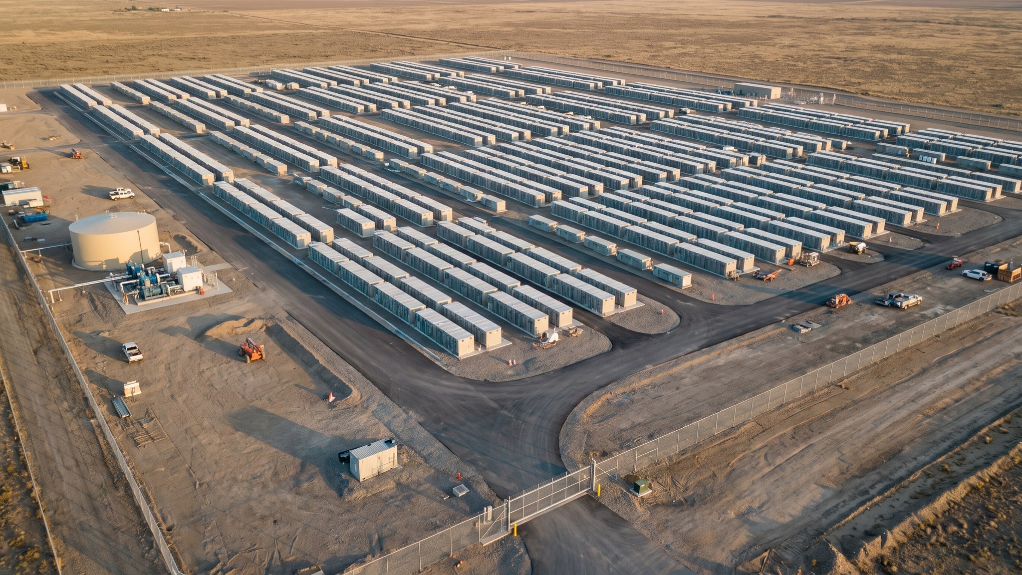
What is Detection, ventilation and pressure management?
A battery cell that begins to fail does not usually go straight to fire. It heats, and it produces gas, and there is a period during which something can be noticed. Detection and ventilation arrangements exist to use that period: to identify an event as early as possible, to alert the people who need to know, to allow the site controller to act, and to manage the gas that has been produced so that it does not accumulate inside an enclosure. This is the part of the fire strategy that operates before anything is burning, and on a well-designed site it is the part that most often prevents the rest of the strategy from ever being needed.
The reason it matters is the nature of the gas. A failing lithium cell produces gas that is both toxic and flammable, and an accumulation of it inside a closed enclosure is a hazard in its own right, separate from any fire. Managing that accumulation, and managing the pressure that comes with it, is therefore a designed function of the enclosure rather than an accessory. It is also the reason the fire and rescue service is consulted about these sites early: what they may face is not a conventional fire, the gas can persist, and a battery that has apparently been dealt with can reignite. Understanding that before an incident is materially different from discovering it during one.
How any of this is achieved on a particular project is a matter for the fire engineer and the equipment manufacturer, and it is deliberately not described here. What detects, what it responds to, at what point it acts, what happens then, how the enclosure is ventilated, how pressure is managed and how the arrangements are proved are all specific to the units installed and the assessment carried out, and are recorded in the specification for that project. What can usefully be said in general is that these are engineered systems with a defined design intent; that they must be proved to work before the site is operated and re-proved through its life; that they interact with the layout, the barriers and the water and access provisions rather than standing alone; and that they are only as good as the maintenance regime the operator actually runs.
How does Detection, ventilation and pressure management work, step by step?
- 1
Step 1: Start from how the units behave
The fire engineer works from the manufacturer's evidence about how the specific units behave when a cell fails: what they produce, in what sequence, and what the enclosure is designed to do about it. The detection and ventilation strategy is derived from that evidence. It cannot be copied from another product or another site, and where the evidence is limited the strategy becomes more conservative.
- 2
Step 2: Define what the arrangements are for
Before anything is specified, the design intent is written down: what an early event should cause to happen, who should be told, what the site should do automatically, and what the arrangements are not intended to achieve. Being explicit about the limits matters as much as the capabilities, because it is what stops an operator or a responder assuming a protection that does not exist.
- 3
Step 3: Design detection into the enclosure
Detection is designed as part of the enclosure and its control system by the fire engineer with the manufacturer, and is generally not something added to a finished product by a third party. What it monitors, where it is located and how it is arranged all follow from the assessment. The thresholds and settings themselves belong to that design and are recorded in the project specification rather than published.
- 4
Step 4: Design the ventilation and pressure arrangements
The enclosure has to deal with gas that is produced inside it and with the pressure that accompanies it. How that is done is an engineered function of the enclosure, designed by the fire engineer with the manufacturer, and it constrains the site layout because it determines where gas may be released and therefore what may be positioned nearby. Layout decisions taken without reference to those arrangements are a common and serious error.
- 5
Step 5: Connect the arrangements to the site response
Detection is only useful if something happens as a result. The design sets out what is signalled, to whom, and what the site control system and the operator do next, including how the fire and rescue service is called and what information they receive. Alarms that arrive somewhere nobody is watching, or that arrive without the information needed to act, are a design failure rather than an operational one.
- 6
Step 6: Consult the fire and rescue service on what they will meet
The fire and rescue service is told during design what these arrangements do, what an incident is likely to look like, and why a lithium battery event is not a conventional fire - it produces toxic and flammable gas, it is difficult to extinguish, and it can reignite after it appears to be out. That understanding shapes their planning for the site. It is provided as site information for their planning, not as instruction, and their operational decisions remain entirely theirs.
- 7
Step 7: Prove the arrangements before operation
The arrangements are proved to work before the site operates, in a sequence and to criteria set by the fire engineer and the manufacturer and witnessed as the specification requires. The results are recorded and form part of the evidence that the site is fit to operate. Proving is not a formality: it is where the difference between a designed system and an installed system is discovered.
- 8
Step 8: Maintain and re-prove through life
These are systems, and systems degrade. The maintenance regime, the re-testing intervals and the responsibility for them are handed over with the asset and written into the operating documentation. Changes to the units, to the control system or to the layout require the arrangements to be reviewed. A detection system that has not been maintained is worse than none, because the site has been operating on the assumption that it works.
What are the benefits of Detection, ventilation and pressure management?
- Acts during the period before an event becomes a fire, when intervention is still possible
- Alerts the operator and the fire and rescue service early rather than late
- Manages gas accumulation inside the enclosure, which is a hazard in its own right
- Provides information that helps responders understand what they are dealing with
- Works alongside layout and barrier measures rather than duplicating them
- Can prevent a single cell failure from ever becoming a site incident
What are the limitations of Detection, ventilation and pressure management?
- Depends on equipment working, and therefore on maintenance being carried out
- Arrangements are specific to the units installed and do not transfer between products
- Ventilation and pressure arrangements constrain what can be positioned nearby
- Alarms are only useful if they reach someone able and equipped to act
- Requires periodic re-proving through the life of the asset
- Cannot make a lithium battery fire behave like a conventional fire
What is Detection, ventilation and pressure management best suited for?
What plant does Detection, ventilation and pressure management need?
- Manufacturer's enclosure equipment installed as part of the unit rather than added later
- Control and communications installation equipment for signalling to the site controller
- Access equipment for installing and later inspecting enclosure-mounted equipment
- Test equipment specified by the fire engineer and the manufacturer for proving
- Recording equipment for the proving evidence
- No site-improvised additions to a manufacturer's designed enclosure arrangements
How is Detection, ventilation and pressure management quality-checked?
- Design intent recorded, including what the arrangements are not intended to achieve
- Installation confirmed as the manufacturer's designed arrangement, with nothing added on site
- Layout checked against the enclosure's ventilation and pressure arrangements
- Signalling path proved end to end to a place where someone can act on it
- Proving completed and witnessed as the specification requires before operation
- Maintenance and re-proving regime handed over with named responsibility