Rainwater harvesting
Catch it off the roof, filter it, store it, pump it back for the uses that do not need drinking water - and never let the two systems meet.
Last updated 2026-09-05
What is Rainwater harvesting?
A rainwater harvesting system collects rain from the roof of a building, filters and stores it, and pumps it back into the building for uses that do not require drinking water - typically flushing, irrigation, vehicle washing and some process and cleaning duties. The idea is simple and the components are ordinary: gutters and downpipes that already exist, a filter, a tank, a pump set, a control panel and a separate distribution pipework system. What makes it a specialist installation is not the plant. It is the absolute requirement that the harvested water and the drinking water systems in the building can never, under any condition, be connected.
Roofs are the collection surface because they are relatively clean and the run-off is reasonably predictable. Paved areas and car parks are not normally used because the run-off carries oils, silts and contaminants that the treatment is not designed for. The size of the collection area, the local rainfall and the demand from the non-potable fittings together determine how much of the demand a system can realistically meet, and the balance between those three is a calculation the designer performs for the specific building. Storage sits either below ground in a buried tank, which is the common arrangement where there is external space and where the ground conditions allow, or above ground in a plant room or externally, which is simpler to install and inspect but takes up usable space and needs a structure that can carry the load.
In practice these systems are usually driven by planning conditions or by sustainability assessment credits rather than by a straightforward payback on the water bill. That matters because it shapes the specification: a system installed to earn a credit still has to be maintained for the life of the building, and the maintenance burden - filter cleaning, tank inspection, pump servicing, control checks and periodic water quality attention - is a real and permanent cost that the client should understand before handover rather than discover afterwards. The systems that fail are almost never the ones that were badly installed. They are the ones that nobody maintained, that were bypassed after the first fault, and that ended up as a buried tank full of stagnant water feeding nothing.
How does Rainwater harvesting work, step by step?
- 1
Step 1: Establish the demand and the yield
The designer works out how much non-potable water the building will actually use - which fittings and outlets will be served, and at what pattern of demand - and how much rain the collection roof can be expected to deliver over the year. The two are then reconciled against a storage volume that carries the system through dry periods without becoming so large that the water sits stagnant. The result also tells the client what proportion of demand the system will meet, which is usually rather less than people expect. All of these figures are specific to the building, the roof area and the location, and they come out of the designer's calculation rather than off a chart.
- 2
Step 2: Design the collection and filtration arrangement
Only suitable roof areas are collected from. Downpipes serving those areas are routed to the filter, and downpipes serving unsuitable surfaces are kept out of the system entirely. Leaf guards and a first filtration stage remove debris before the water reaches the tank; on many systems an arrangement is included to divert the first, dirtiest flush of a rainfall event to drain rather than into storage. Filters are positioned where they can actually be reached, because a filter that needs a confined space entry or a road closure to clean will not be cleaned. The overflow from the tank is designed as part of the site drainage and discharges to the point the drainage designer has specified.
- 3
Step 3: Install the storage tank
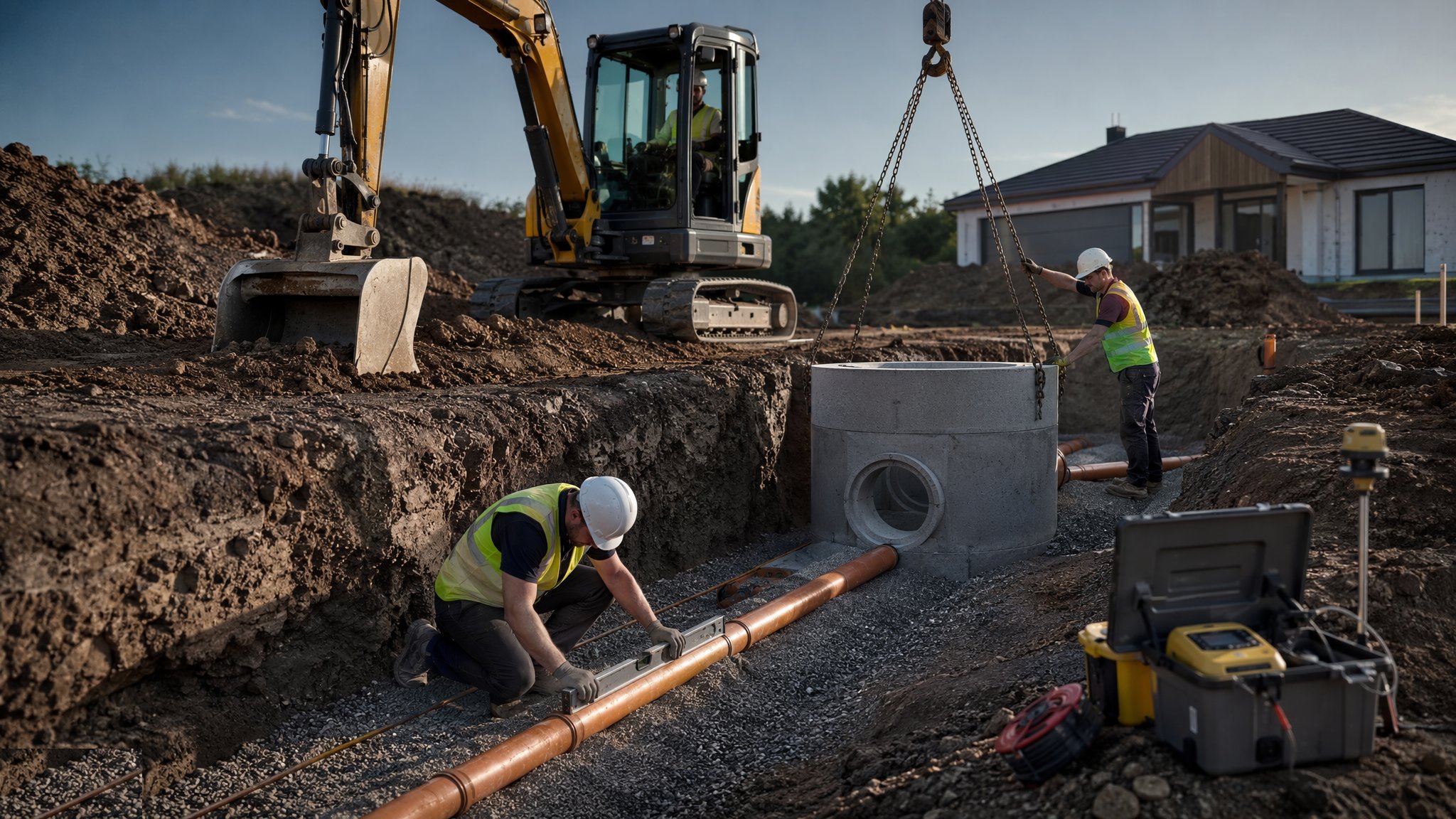
Below-ground tanks are installed as an excavation and bedding operation, set on a prepared base, surrounded and backfilled in the arrangement the tank manufacturer specifies, and provided with an access chamber and cover suitable for whatever will drive over them. Buoyancy has to be considered where the water table is high, because an empty tank in wet ground will float. Above-ground tanks are simpler but need a supporting structure designed for the full weight of water and a location where a leak or an overflow is not a disaster. Either way the tank is dark, vented, insect-proof and accessible for inspection and cleaning, and the inlet is arranged so that incoming water does not stir up the settled material at the bottom.
- 4
Step 4: Install the pump set and controls
A pump takes water from the tank and delivers it to the non-potable outlets, either directly on demand or via a small header arrangement. The control panel manages the pump, monitors the tank level, and switches the supply to mains top-up when the stored water runs out. Controls also cover the alarms - low level, pump fault, overflow - and how those alarms reach somebody who will act on them. Pumps and panels are located where they can be serviced and where noise is not transmitted into occupied space, and the electrical supply and isolation are coordinated with the electrical contractor.
- 5
Step 5: Provide the mains backup through an air gap
When the tank runs dry the non-potable system still has to work, so a mains top-up is provided. The critical point is how that connection is made. The mains supply discharges into a break tank or a top-up chamber across a physical air gap, so that there is no continuous path from the harvested water back into the drinking water supply under any circumstances - not when the pump runs, not when the mains pressure drops, and not when something is left open. A direct connection between the two systems, even through a valve, is not acceptable. This arrangement is designed by the services engineer and inspected as a specific item.
- 6
Step 6: Install and mark the non-potable distribution separately
The harvested water runs in its own pipework, entirely separate from the drinking water system, and that pipework is marked so that nobody who works on the building in future can mistake one for the other. Marking means the specified colour or identification along the whole run, at every accessible point, in every riser and in every plant space - not a label at the pump and nothing beyond it. Outlets served by harvested water carry warning signage indicating that the water is not for drinking, and any outlet that could be used to draw water for washing or drinking is either avoided or clearly identified. Cross connection between the two systems is the one failure mode with a genuine public health consequence, and every control on the installation exists to prevent it.
- 7
Step 7: Commission, label and hand over
Commissioning proves the whole sequence: that the filters pass water and can be removed and cleaned, that the tank fills and overflows to the right place, that the pump delivers to every outlet, that the level controls switch to mains top-up and back again, and that the alarms operate and reach somebody. A cross connection check is carried out as a distinct and recorded item. The handover pack includes the as-installed drawings showing every metre of non-potable pipework, the operating and maintenance instructions, the filter and tank cleaning intervals, the pump service requirements and the labelling schedule. The client is told plainly what the maintenance obligation is.
- 8
Step 8: Maintain it, or lose the benefit
A harvested water system is a live installation, not a buried tank. Filters need cleaning at the intervals the supplier states and more often in autumn. Tanks need periodic inspection and desludging. Pumps and controls need servicing. Water quality needs attention appropriate to the uses served, particularly where water may be sprayed or where the system serves anything beyond flushing and irrigation. The identification and signage need checking after any alteration, because the greatest long-term risk to a building with two water systems is a future contractor who does not know the second one is there.
What are the benefits of Rainwater harvesting?
- Reduces mains water consumption for flushing, irrigation and washing, which on some buildings is a large share of total use
- Attenuates roof run-off, so it can contribute to the site surface water strategy as well as to water use
- Commonly satisfies a planning condition or earns sustainability assessment credits, which is usually what justifies it
- Uses ordinary, well-understood components - filters, tanks, pumps and controls - with no exotic technology
- Below-ground storage takes no usable floor area and is invisible once the ground is reinstated
- Gives the building a supply for irrigation and washing that is unaffected by hosepipe restrictions
What are the limitations of Rainwater harvesting?
- Rarely justified on water cost alone - payback is usually long, and the driver is normally planning or assessment credits
- Meets only part of the non-potable demand, and how much depends on roof area, rainfall and demand pattern
- Adds a permanent maintenance obligation - filters, tank cleaning, pump servicing and control checks - that clients routinely underestimate
- A second, entirely separate distribution system means more pipework, more space, more labelling and more risk of future confusion
- Cross connection to the drinking water system is a public health failure, so separation, marking and inspection are non-negotiable
- Below-ground tanks bring excavation, buoyancy and access chamber issues, and are difficult to alter afterwards
- Pumped supply means the system depends on power and on functioning controls, unlike the mains it partly replaces
- Systems that are neglected become stagnant storage feeding nothing, which is worse than never having installed one
What is Rainwater harvesting best suited for?
What plant does Rainwater harvesting need?
- Leaf guards, downpipe filters and a first-flush diversion arrangement where specified
- Storage tank - buried sectional or moulded tank with access chamber and cover, or an above-ground tank on a designed support
- Calmed inlet, overflow with the appropriate protection, and vent and insect screening
- Pump set with its control panel, level sensors and alarm outputs
- Break tank or top-up chamber providing the mains air gap
- Non-potable distribution pipework in the specified identification colour, with marking tape, labels and warning signage
- Excavation, bedding and backfill plant for below-ground tanks, with dewatering where the water table demands it
- Commissioning instruments and a cross connection checking procedure
How is Rainwater harvesting quality-checked?
- Demand, yield and storage volume calculated by the designer for the specific building and recorded
- Collection restricted to suitable roof areas, with unsuitable downpipes confirmed excluded from the system
- Filter and access chamber positions confirmed as reachable for routine cleaning without special access arrangements
- Tank bedding, surround and backfill installed to the manufacturer's requirements, with buoyancy addressed where the water table is high
- Above-ground tank support structure confirmed by the structural designer for the full weight of water
- Mains top-up proved to be through a physical air gap, inspected and recorded as a specific hold point
- Non-potable pipework identified along its full length, in every riser and plant space, and outlets signed as not for drinking
- Documented cross connection check carried out and recorded before handover
- Pump, level control, mains top-up changeover and alarm functions commissioned and witnessed
- As-installed drawings of all non-potable pipework, plus cleaning intervals, servicing requirements and the labelling schedule, issued to the client at handover