TRVs & lockshields - the standard set
A throttle at one end of the radiator and a balancing valve at the other - and the second one is the one that gets skipped.
Last updated 2026-09-05
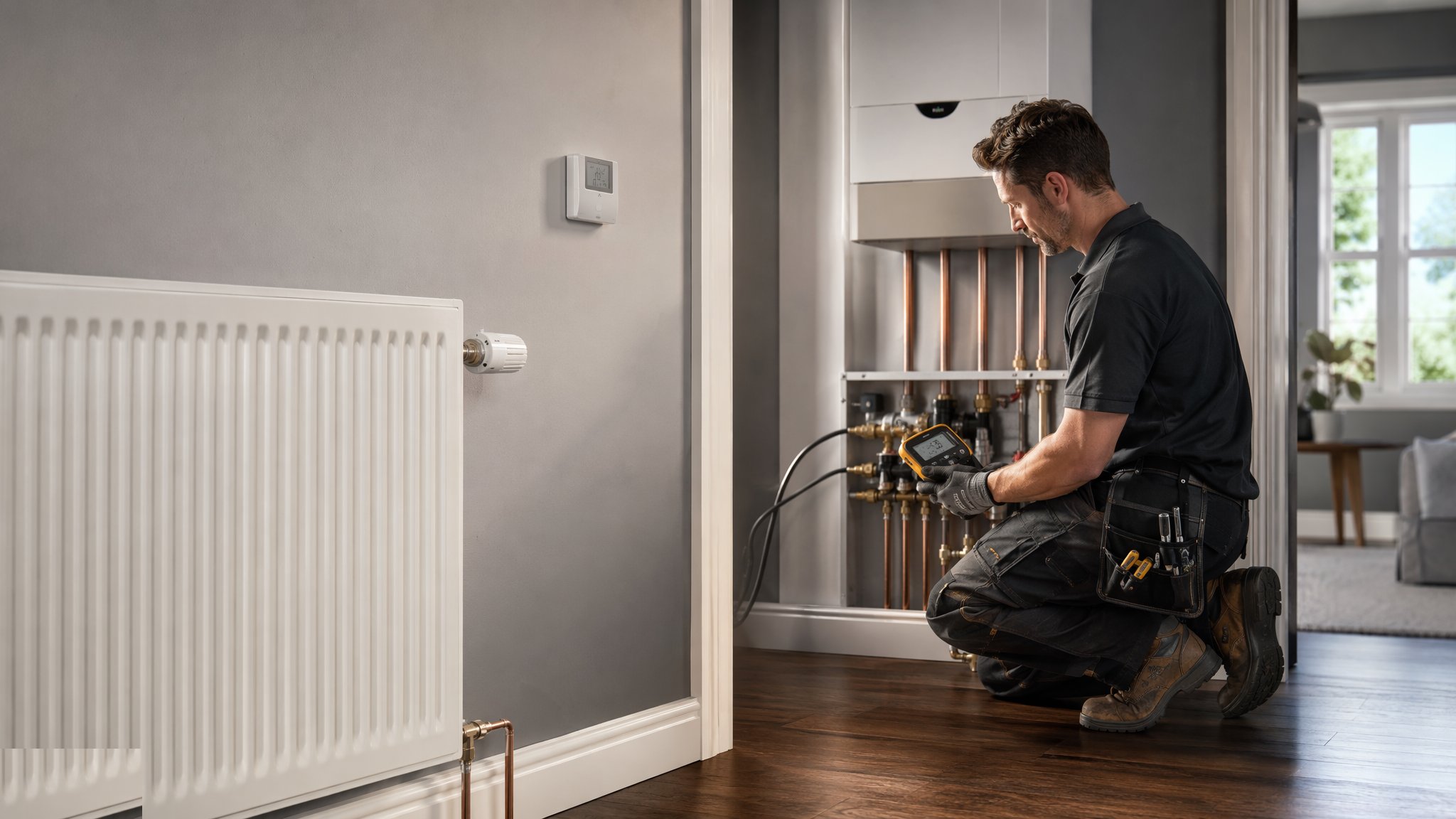
What is TRVs & lockshields - the standard set?
Almost every radiator on a modern wet heating system has two valves, one at each end, and they do completely different jobs. At one end sits the thermostatic radiator valve, usually shortened to TRV on drawings and on site. It is a self-acting control: a sensing element in the head expands as the air around it warms, pushes a pin down into the valve body and throttles the flow through the radiator, then relaxes and reopens as the room cools. Nothing is wired to it and nothing tells it what the rest of the house is doing. It senses one room and reacts to that room, which is why it is best described as a room-temperature-limiting device rather than a thermostat in the proper sense. At the other end sits the lockshield, a plain valve with a plastic cap over the spindle. The cap is there to stop people turning it. The lockshield is not a user control at all - it is the balancing valve, set once at commissioning and then left alone.
The two valves together are what makes a radiator circuit behave. Water is lazy and takes the shortest, easiest route back to the boiler, so on an unbalanced system the radiators nearest the plant take far more than their share of the flow and the ones at the end of the run get whatever is left, which is often not much. Balancing is the process of deliberately restricting the easy circuits at the lockshield so that every radiator receives a sensible share and every radiator warms at roughly the same rate. It is the single step most often left out on a rushed handover, and the symptom is entirely predictable: the front room is hot within minutes, the far bedroom or the one over the garage never really gets going, and somebody spends the next winter turning the boiler up to solve a distribution problem. Turning the heat source up does not fix an unbalanced system. It just makes the near radiators hotter.
On most projects the set is straightforward to install and easy to get slightly wrong. Valve bodies are handed for flow direction on some patterns and bidirectional on others, so the specification and the valve markings decide which end the TRV goes on. Head orientation matters because the sensing element has to sit in moving room air rather than in the plume of hot air rising off the radiator itself, which is why horizontal pipework at low level usually suits a horizontal head and a vertical drop suits an upright one, and why a TRV tucked behind a long curtain or inside a boxed pipe casing will always read the wrong thing. There is one more principle that sits behind the whole arrangement. If every TRV on the system closes at once, the pump can end up with nowhere to push water, so the design has to keep a guaranteed path open. On many domestic layouts that is done by leaving one or more radiators without a TRV, and on others it is a dedicated bypass arrangement or a pump that recognises the condition and responds. Which route is used is the designer's call, and it is set out in the specification rather than decided on site.
How does TRVs & lockshields - the standard set work, step by step?
- 1
Step 1: Read the design before opening the boxes
The heating layout tells you which rooms get a TRV, which radiators are deliberately left without one, where the bypass or pump-protection arrangement sits, and what the balancing intent is. It also tells you the flow direction of the circuit, which decides the handing of the valve bodies. Rooms with their own wall thermostat are commonly left off the TRV schedule so that two controls are not fighting over the same air, and bathrooms are often treated as a special case for the same reason. None of that is obvious from the pipework alone, so the schedule is read first and any conflict is raised with the services engineer rather than resolved with a guess.
- 2
Step 2: Fit the valve bodies to the radiator tails
The bodies go on at first fix or when the radiators are hung, made off onto the radiator tails with the jointing method the specification calls for and pulled up square so the valve is not carrying any strain from the pipework. Getting them plumb and at a consistent height across a plot is not vanity - it is what makes the second-fix connection land cleanly and what an inspector will look at first. On a repeat housing project the valve positions are usually set from a standard detail so that every plot is the same, which makes the later balancing and any future maintenance far quicker.
- 3
Step 3: Set the lockshields to a starting position
Before the system is filled, the lockshields are commonly opened to a nominal starting position rather than left fully open, so that balancing begins from a known point rather than from wherever the valve happened to arrive. The number of turns used as the starting point comes from the commissioning intent for that system, not from habit. It is only a start, and it will change. The point is that the whole system starts in the same condition so that the adjustments made later mean something.
- 4
Step 4: Fill, vent and flush before anything is judged
Air in a radiator looks exactly like a balancing problem, and debris in a valve looks like a faulty valve. So the system is filled, vented at every high point and cleaned in line with the specification before any judgement is made about flow distribution. Water treatment and any strainer or filtration arrangement go in at this stage too. Trying to balance a dirty or airlocked system wastes a day and produces settings that are wrong the moment the air clears.
- 5
Step 5: Bring the heat source on under a competent person
Firing the heat source for the first time is not part of the radiator fitter's work. Commissioning a boiler or any gas appliance is work for a suitably qualified and registered engineer, and the electrical connections into the controls are for a competent qualified electrician. The plumbing crew present the system full, vented and pressure-tested, and the appliance is brought into use by the person entitled to do it. On most projects that sequence is written into the programme, because a system that is not ready wastes the visit.
- 6
Step 6: Balance the system radiator by radiator
With the system up to its design condition, the commissioning engineer works round the circuits adjusting each lockshield so that flow is shared as the design intends, typically checking the temperature difference across each radiator between the flow and return tails and closing down the near, favoured circuits until the far ones respond. It is iterative - closing one valve changes every other - so the round is repeated until the whole system settles. The target figures belong to the design and the commissioning specification for that particular system. What matters on site is that the process is actually carried out and that the settings are recorded, because an unrecorded balance is one service visit away from being lost.
- 7
Step 7: Fit the heads and set the orientation
TRV heads go on at the end, commonly after decoration, so that they are not painted, damaged or stolen. Each head is fitted so the sensing element sits in free room air, clear of the radiator's own convected heat, clear of curtains, furniture and pipe casings, and readable from standing height. Where the position of the valve makes that impossible, a remote sensor or a head on a capillary is the usual answer and it is agreed with the designer rather than improvised. Heads are then set to the commissioning position and, on many projects, limited or pinned so that occupants cannot drive every room to maximum on day one.
- 8
Step 8: Record it and show the client
The commissioning record captures the lockshield settings, the balancing results and the head positions, and it goes into the handover file with the rest of the heating information. Five minutes explaining to the occupant that the numbered head controls the room and the capped valve is not theirs to touch prevents a great many callbacks. The most common defect reported in the first winter is not a failed valve at all - it is somebody having turned a lockshield or moved a head, and a system that has never been balanced properly showing the strain.
What are the benefits of TRVs & lockshields - the standard set?
- Gives room-by-room temperature limiting for a very low cost per radiator, with no wiring and no power supply
- Lets unused and overheated rooms be turned down without affecting the rest of the dwelling
- The lockshield gives the commissioning engineer a direct, mechanical way to fix uneven distribution
- Simple, well-understood components that almost any maintenance operative can service or replace
- A properly balanced set makes the whole system quieter, more even and less prone to the near-hot far-cold complaint
- Works with almost any wet heat source and is easily added to an existing system a radiator at a time
What are the limitations of TRVs & lockshields - the standard set?
- A TRV senses the air around itself, not the room average, so a head behind a curtain or in a pipe boxing controls the wrong thing
- It only throttles flow - it cannot call the heat source on, so it is never a substitute for time and temperature control
- Balancing is skipped on a great many projects, and without it the far radiators stay cold whatever the heads are set to
- Settings drift when occupants move heads or unlock a lockshield, and there is nothing on the valve to show it has happened
- Pins and sensing elements seize when a system stands idle over summer, which is why they are the classic first-cold-morning failure
- Two controls in one room, a TRV and a wall thermostat, will work against each other unless the design deliberately separates them
What is TRVs & lockshields - the standard set best suited for?
What plant does TRVs & lockshields - the standard set need?
- TRV bodies and heads, and lockshield valves, matched to the pipe size and the flow direction on the drawing
- Pipe cutters, bending and jointing equipment appropriate to the pipework material and the specified joint
- Radiator brackets, fixings and a level, with a standard detail for repeat plots
- Filling, venting and pressure-testing equipment, plus the flushing and water treatment arrangement the specification requires
- Clamp-on or contact thermometers for the balancing round, and a commissioning record sheet
- Head-removal and setting tools, and any locking or limiting components called for in the specification
How is TRVs & lockshields - the standard set quality-checked?
- Valve handing checked against the flow direction and the manufacturer's markings before the bodies are made off
- Radiators and valves set plumb, square and to consistent heights across repeated plots
- System filled, vented, cleaned and pressure-tested, with the results recorded, before any balancing is attempted
- Boiler or appliance commissioning and any live electrical connection carried out only by the qualified person entitled to do it
- Balancing round completed and repeated until the system settles, with every lockshield setting written down
- Heads fitted clear of curtains, casings and the radiator plume, set to the commissioning position, and explained to the occupant at handover
More trvs & heating controls methods
Next method
Programmers, stats & smart controls