Zoned systems & UFH manifolds
Splitting a building into separately controlled areas, and the manifold that does the same job for underfloor circuits.
Last updated 2026-09-05
What is Zoned systems & UFH manifolds?
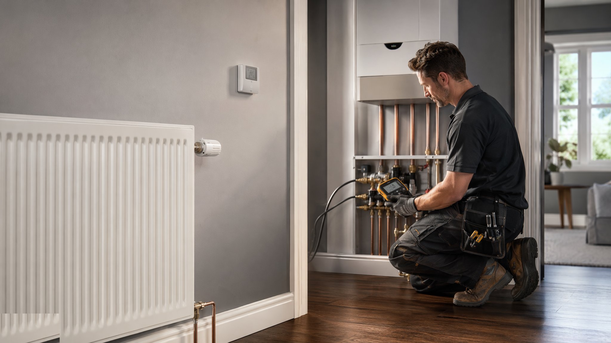
Zoning means dividing a building into areas that can be heated independently, each with its own temperature sensing and its own means of shutting off. In a radiator system the shut-off is a motorised zone valve on the pipework serving that area, wired so that a call for heat from that zone's thermostat opens the valve and, through an end switch, tells the heat source and the pump to run. A common arrangement in a house splits upstairs from downstairs, or splits the heating from the stored hot water, so that a bedroom floor does not have to be heated because somebody is sitting in the living room. Larger dwellings and apartments over several levels take the same idea further. The principle never changes: a zone is an area with its own sensor, its own valve and its own schedule, and a zone without all three is not really a zone.
Underfloor heating does the same thing through a manifold, and the manifold is the heart of the installation. Continuous loops of pipe are laid in the floor build-up and both ends of every loop return to a manifold cabinet. On the flow bar sits a flow meter or a regulating device for each loop, which is how the circuits are balanced against each other - loops in a floor are never the same length, and without balancing the short ones take everything. On the return bar sits a small electrothermal actuator for each loop, which opens and closes that circuit on a call from the room it serves. Because a floor cannot be run at the same temperature as a radiator circuit, the manifold usually carries a mixing arrangement with its own pump and a blending valve that brings the circuit temperature down to what the floor construction can take. That circuit temperature is the designer's figure, based on the floor build-up, the finish and the heat output required, and it is set at commissioning by the commissioning engineer rather than adjusted by anyone else afterwards.
What makes underfloor different to live with is thermal mass. A radiator responds in minutes; a heated screed responds over hours, and it keeps giving out heat long after the call has stopped. That single fact changes the controls strategy. Schedules run ahead of occupancy rather than with it, setbacks are shallow rather than deep because recovering a cold slab is slow and expensive, and controls that learn or anticipate earn their keep here far more than on a radiator system. The floor construction drives it too: a screed of any depth is slow and steady, while a low-profile panel system or a suspended timber floor with spreader plates responds much faster and behaves more like a radiator. Floor finishes matter as much - the designer will confirm which coverings suit, because a thick insulating covering laid over a heated floor undoes the design, and timber and some resilient finishes bring their own restrictions on temperature and on how the floor is brought up to heat for the first time. Getting all of that agreed before the screed goes down is the difference between a system that works and one that can never be fixed without lifting the floor.
How does Zoned systems & UFH manifolds work, step by step?
- 1
Step 1: Agree the zones and the sensing before first fix
The designer sets out how the building divides: which areas are zones, where each zone's sensor goes, which zones are underfloor and which are radiator, and how hot water fits into the scheme. Each zone needs a sensor position that represents it, and rooms with their own underfloor loops need to be identified against the manifold. This is settled on paper because it drives the pipework routes, the valve positions, the cable runs and the manifold locations, and almost none of it can be changed once the floor is closed.
- 2
Step 2: Site the manifold cabinets and the zone valves for access
A manifold has to be reachable for the life of the building - for balancing, for actuator replacement and for filling and venting - so cabinets go in agreed, accessible positions with room to work in front of them, not in the back of a cupboard that will be filled with the client's belongings by the end of the first month. Motorised zone valves are sited so the head can be removed and the manual lever reached. Getting the cabinet position agreed with the architect early avoids a late argument about a panel in a hallway.
- 3
Step 3: Prepare the floor build-up and lay the loops
Underfloor pipework sits on a prepared, insulated build-up in the arrangement the design specifies, with the loops set out to the design layout and lengths, fixed down so that they cannot float or move when the screed is placed, and with the spacing tightened where the design calls for more output. Every loop returns to its manifold and is labelled to its room as it is connected. Movement joints in the floor and the crossing details at doorways are followed as drawn. Loops are commonly pressurised and left under test pressure through the screed pour so that any damage shows up immediately rather than after the floor has set.
- 4
Step 4: Connect and pressure-test before the floor is closed
Each loop is connected to the flow and return bars, filled, vented and pressure-tested, and the test is recorded with a photographic set-out record of the loop layout before covering. That record is worth more than any other document on the project the first time somebody wants to fix a shelf into a heated floor. Nothing is covered until the test result is in, because a leak found under a finished screed is a very expensive discovery.
- 5
Step 5: Let the screed cure, then commission the floor gradually
Screed needs its own curing period before any heat is applied, and the period comes from the screed specification. The first heat-up is then a controlled procedure, brought on gradually and held at increasing steps over a period of days in line with the designer's and the screed supplier's requirements, so that the floor dries and moves without cracking. Where a timber or resilient finish is to be laid, this commissioning heat cycle is normally completed and the floor moisture proved before the finish goes down. Rushing it is the origin of most cracked screeds and lifted floor finishes on underfloor projects.
- 6
Step 6: Set up the mixing arrangement and balance the loops
The commissioning engineer sets the blending arrangement so the circuit runs at the temperature the designer specified for that floor build-up, proves the manifold pump, and then balances the loops against one another using the flow devices on the flow bar so that the long circuits are not starved by the short ones. The figures come from the loop schedule prepared by the designer. As with radiator balancing it is iterative and it is recorded, and an unrecorded set of flow settings is lost the first time somebody drains the system.
- 7
Step 7: Wire the actuators, valves and zone controls
Actuators, zone valves, the manifold pump and each zone thermostat are wired back through a wiring centre so that a call from a room opens the right actuator, and a call from any zone brings on the pump and the heat source through the appropriate interlocks. All of it is work for a competent qualified electrician working to the wiring diagram. Actuators are then proved individually - operating one zone and confirming that the correct loop, and only the correct loop, warms - because crossed actuators are a very common defect and one that is almost impossible to diagnose from the room.
- 8
Step 8: Tune the schedules to the response of the system
Once the system is proved, the schedules are set to suit how the building responds rather than copied from a radiator system. Underfloor zones are typically brought on well ahead of occupancy and run on a shallow setback rather than switched hard on and off, and mixed systems need the fast radiator zones and the slow floor zones scheduled differently. The client is then shown why the floor does not respond immediately to a boost, which is far and away the most common first-winter complaint on an underfloor system and is almost never a fault.
What are the benefits of Zoned systems & UFH manifolds?
- Unoccupied areas can be shut off completely rather than heated to keep one room comfortable
- Each zone gets its own schedule, so sleeping areas and living areas can run on entirely different patterns
- Underfloor circuits run at a lower temperature, which suits low-temperature heat sources very well
- A heated floor gives even, draught-free warmth with no radiators taking up wall space
- Flow devices at the manifold make balancing measurable and repeatable rather than a matter of feel
- Zone valves and actuators let a single heat source serve areas with very different demands
What are the limitations of Zoned systems & UFH manifolds?
- The pipework, sensor positions and zone split are effectively permanent once the floor is closed
- Thermal mass makes a screed floor slow to respond, so boost and deep setback behave badly and clients read that as a fault
- Floor finishes constrain the design, and an insulating covering laid over a heated floor undoes the output it was designed for
- Screed curing and the controlled first heat-up occupy real programme time that is often not allowed for
- More components means more to go wrong - actuators, the manifold pump and the blending arrangement all add failure points
- Crossed actuators and unlabelled loops are common defects and are very hard to unpick after handover
What is Zoned systems & UFH manifolds best suited for?
What plant does Zoned systems & UFH manifolds need?
- Manifold assemblies with flow devices, actuators, isolation, filling and venting points, in accessible cabinets
- Blending or mixing arrangement with its circulating pump and temperature indication
- Continuous loop pipework, floor insulation, fixing systems, edge and movement details
- Motorised zone valves, zone thermostats, wiring centre and control cabling
- Pressure-testing equipment and a photographic loop set-out record made before covering
- Commissioning instruments for flow setting and temperature checks, and the loop schedule to set them against
How is Zoned systems & UFH manifolds quality-checked?
- Zone split, sensor positions and loop layout confirmed against the design before any floor is closed
- Every loop labelled to its room at the manifold, and the set-out recorded photographically before covering
- Loops pressure-tested and held under pressure through the screed pour, with the results recorded
- Screed curing period observed and the controlled first heat-up carried out to the specified regime and documented
- Circuit temperature set by the commissioning engineer to the designer's figure, and loop flows balanced and recorded
- Each actuator and zone valve proved individually against its room, and the schedules tuned to the response of the system before handover