Composite steel-concrete frame
Metal deck and concrete acting together with the steel beams through shear studs - a fast frame that only becomes composite once the concrete has gained strength.
Last updated 2026-09-05
What is Composite steel-concrete frame?
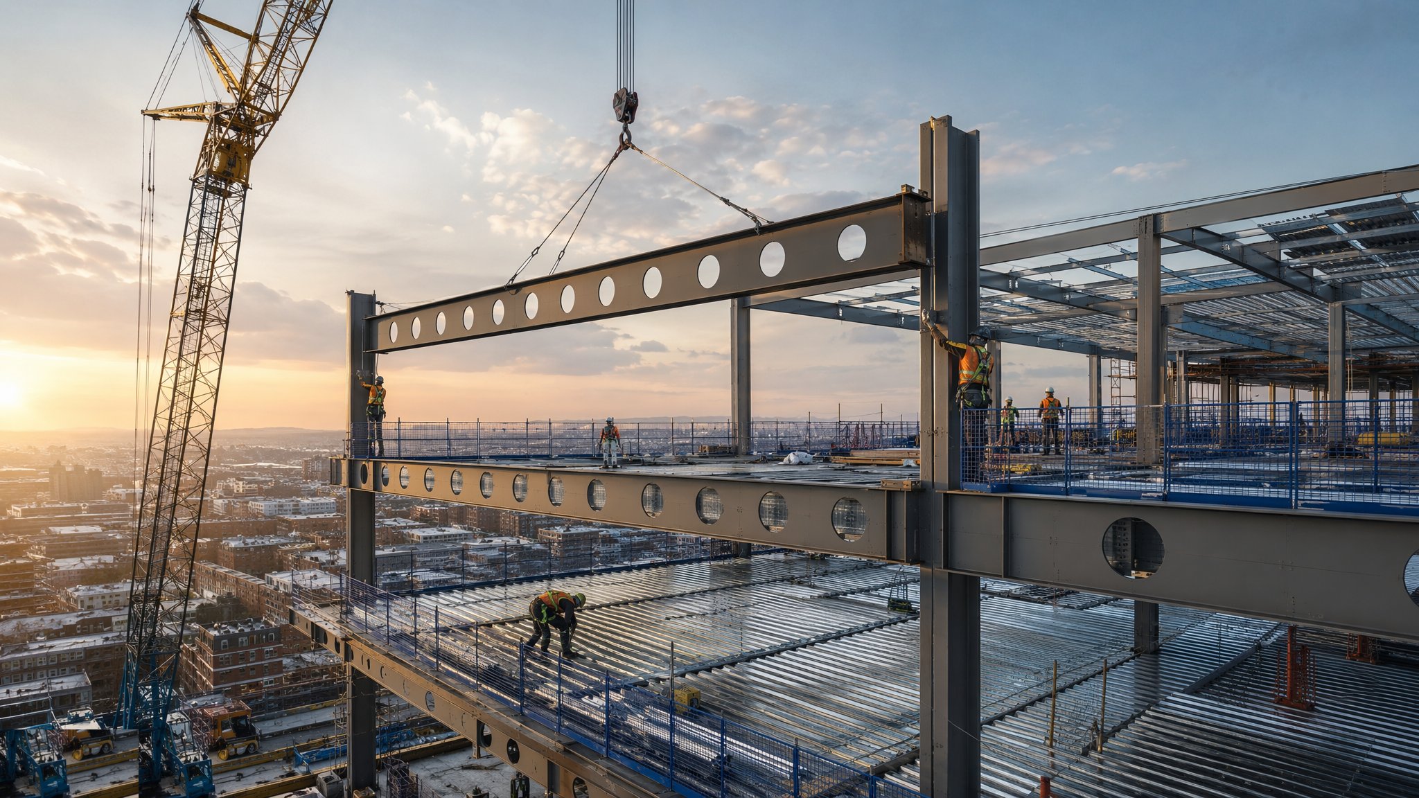
A composite frame is a steel frame whose floor slab is deliberately made to work with the steelwork rather than just sit on it. Profiled metal decking spans between the beams and acts as permanent formwork, reinforcement is laid in, and concrete is placed over the top to form a slab. What makes it composite is the shear connection: studs welded through the deck onto the top flange of the beam so that the slab and the beam cannot slide past one another under load. Tie the two together and the concrete works in compression while the steel works in tension, and the pair carries far more than either would on its own. That is why composite floors are the standard commercial floor in the UK. It is a genuinely efficient use of both materials and it comes with almost none of the programme cost of a wet trade, because the deck is dry, light and installed by the same gang that follows the steel.
The other half of the argument is the working platform. Decking is landed in bundles by the crane, laid out and fixed down floor by floor as the frame rises, so within days of a level being bolted up there is a continuous safe surface to work from, with edge protection around it. Following trades get access far earlier than they would on a frame with a traditional formed slab, and the concrete pours can be run as a separate operation behind the erection front rather than holding it up. That decoupling is worth a great deal on a tight programme. The deck also does useful work in the finished building: it forms the soffit, it can be left exposed in some applications, and the ribs give somewhere to fix hangers for services and ceilings.
The critical thing everybody on site needs to hold onto is that the frame is not composite until the concrete has gained strength. Before that, the steel beam is carrying the whole of the wet concrete, the deck, the reinforcement and the gang, entirely on its own. That single fact drives the propped-versus-unpropped decision. On an unpropped floor the bare steel beam and the deck are designed to carry the construction stage alone, which keeps the level below completely clear and is the reason most commercial projects prefer it. On a propped floor temporary props take part of the construction load, which allows a lighter steel section or a longer span but ties up the floor below and adds a striking operation to the programme. The choice belongs to the structural engineer and it is made at design stage, not on site, and the propping arrangement and when it may be removed are the temporary works designer's to specify. A propped floor loaded or struck early is one of the classic ways to hurt people on a commercial frame, which is why nobody touches a prop without the written authority of the temporary works designer.
How does Composite steel-concrete frame work, step by step?
- 1
Step 1: Design the floor with the frame, not after it
The composite floor is designed alongside the steel frame because the two are one structural system. The structural engineer sets the beam sizes, the deck profile and gauge, the slab depth, the reinforcement and the shear connection together, working from the grid, the imposed loads, the fire strategy and the acoustic and vibration requirements of the finished building. Floor vibration matters more in a modern office than most people expect, particularly on long, lightly damped spans, and it often influences the design as much as strength does. The propped or unpropped decision is taken here as well, because it changes the steel sizes and it changes what happens on site.
- 2
Step 2: Erect the frame and land the decking
The steel goes up first and the decking follows it closely, usually within a level or two. Bundles are craned onto the frame at planned landing points that the engineer has confirmed can take the bundle load, because a stacked bundle of deck is a heavy concentrated load on a bare beam. Sheets are laid out to the deck layout drawing, run in the direction the design requires, and lapped and seated on the supporting steel by the bearing the manufacturer and the designer call for. Working on part-laid decking is a fall risk until it is fixed, so the gang works to a method that keeps them on fixed material with edge protection and, where needed, fall arrest in place.
- 3
Step 3: Fix the deck down and weld the shear studs
The deck is fixed to the steel and along its side laps so that it acts as a diaphragm and so that no sheet can lift or shift under the gang or the pour. Shear studs are then welded through the deck onto the beam flange, on the pattern the engineer has specified. Stud welding is sensitive to conditions - the steel has to be clean and dry, the deck has to be pulled tight down onto the flange, and galvanised coatings and moisture both interfere with the weld. Studs are tested by bend testing on a sample basis as the work proceeds and the results are recorded. A stud that has not welded properly is a shear connection that does not exist, and the composite action the whole design depends on quietly disappears.
- 4
Step 4: Set the props where the design calls for them
On a propped design, temporary props and bearers are installed under the deck before any concrete is placed, to a scheme produced by the temporary works designer. The props take part of the construction load and reduce deflection of the bare steel, which is what allows the lighter section. The scheme sets the props out, defines what they bear on, and requires that the floor below can take the load being passed down to it - a point missed on more projects than it should be, because props transmit load down through the structure, not into thin air. The props are inspected and signed off before the pour, and they are not moved, adjusted or borrowed for anything else afterwards.
- 5
Step 5: Fix the reinforcement and form the penetrations
Mesh and any additional reinforcement are placed to the drawings, at the cover the specification requires, on proper spacers rather than on offcuts. Edge trim is fixed around the slab perimeter and around every opening, and the penetrations for risers, ducts and drainage are formed now, from the coordinated drawings. Forming holes properly at this stage is far cheaper and far safer than cutting them later, and cutting a composite slab afterwards means cutting the deck, which is structure. Every opening formed in the deck is a fall risk from the moment it exists, so it is covered or protected as it is created.
- 6
Step 6: Place, finish and cure the concrete
Concrete is placed to the pour sequence agreed with the engineer, usually by pump, and spread evenly rather than being heaped in one place, because a heap of wet concrete on an unpropped deck is a construction-stage overload waiting to happen. The slab is levelled and finished to the flatness the specification requires - a poor floor here is an expensive problem for the fit-out - and then cured properly. Curing is not optional. A slab that dries out too fast is a slab that cracks and a slab that has not developed the strength assumed. Cubes are taken from the pour so that strength gain can be demonstrated rather than guessed.
- 7
Step 7: Wait for strength before the floor is composite
Until the concrete has gained the strength the engineer requires, the floor is not the structure shown on the drawing. Loading out a freshly poured floor with materials, plant or stacked pallets is one of the most common ways a well-designed composite floor gets damaged, and the loading limits during this period are the engineer's to set. Where props have been used, they stay in place until the engineer or the temporary works designer confirms in writing that they can come out, and they are struck in the sequence that scheme sets. Nobody on site decides that a slab looks hard enough. The evidence is the cube results and the designer's written release.
- 8
Step 8: Protect the floor and hand it on
Once released, the floor becomes the working deck for every trade above and below it. The soffit is fire protected to the fire strategy, the perimeter is closed for the facade, and the slab surface is protected from the damage that follows a busy fit-out. Levels and flatness are surveyed and recorded, because raised access floors, screeds and finishes are all set out from them. Any subsequent request to cut, core or penetrate the slab goes to the structural engineer, since the deck below the concrete is a structural element and severing it in the wrong place removes capacity the design is relying on.
What are the benefits of Composite steel-concrete frame?
- Steel and concrete each work where they are strongest, giving an efficient floor for the material used
- The metal deck is permanent formwork, so the wet trade is a single pour with no soffit shuttering to erect or strike
- Each level becomes a safe working platform very quickly, and the concrete pours run behind the erection front rather than holding it up
- Concrete adds fire resistance, mass, acoustic separation and stiffness to a lightweight frame
- Unpropped construction leaves the floor below completely clear, which is worth real time on a busy site
- Deck ribs give a ready fixing zone for services hangers and ceiling systems
- Slab depths are modest, keeping the floor zone and the overall building height down
What are the limitations of Composite steel-concrete frame?
- The frame is not composite until the concrete has gained strength - the bare steel carries the whole construction load until then
- Shear studs are the entire basis of composite action and a poorly welded stud is a connection that is not there
- Stud welding is sensitive to wet, dirty or coated steel, so weather and preparation directly affect quality
- Propped designs tie up the floor below and add a striking operation that must follow the temporary works designer's scheme
- Wet concrete on the frame introduces a pour, a curing period and cube testing into an otherwise dry programme
- Slab penetrations cut after the pour sever the deck, which is structure, so they need the engineer's agreement
- Long, lightly damped composite spans can be governed by floor vibration rather than strength
What is Composite steel-concrete frame best suited for?
What plant does Composite steel-concrete frame need?
- Crane for steel erection and for landing decking bundles at approved landing points
- Deck laying and fixing tools, side lap fasteners and edge trim
- Stud welding equipment with its power supply, plus bend test gear for sample testing
- Concrete pump or skips, with placing booms where the reach demands it
- Power floats, laser screeds and levelling equipment for the floor finish
- Temporary props, bearers and forkheads where the design is propped, to the temporary works scheme
- Cube moulds, curing tank and testing arrangements, plus curing membranes or covers
How is Composite steel-concrete frame quality-checked?
- Deck profile, gauge, span direction and end bearing checked against the deck layout drawing before fixing
- Bundle landing positions confirmed by the engineer so that stacked deck does not overload bare steel
- Shear stud pattern, condition of the steel before welding, and sample bend testing recorded as the work proceeds
- Reinforcement, cover and spacers inspected before the pour, with penetrations formed to the coordinated drawings
- Propping installed to the temporary works scheme and inspected and signed off before any concrete is placed
- Concrete cubes taken and tested, with strength gain demonstrated before the floor is treated as composite
- Props struck only on the written authority of the temporary works designer, in the sequence specified
- Floor levels and flatness surveyed against the specification and issued to the finishing trades