Cut-off and recharge
Wall the water out, and put back what the drawdown would have stolen from next door.
Last updated 2026-08-22

What is Cut-off and recharge?
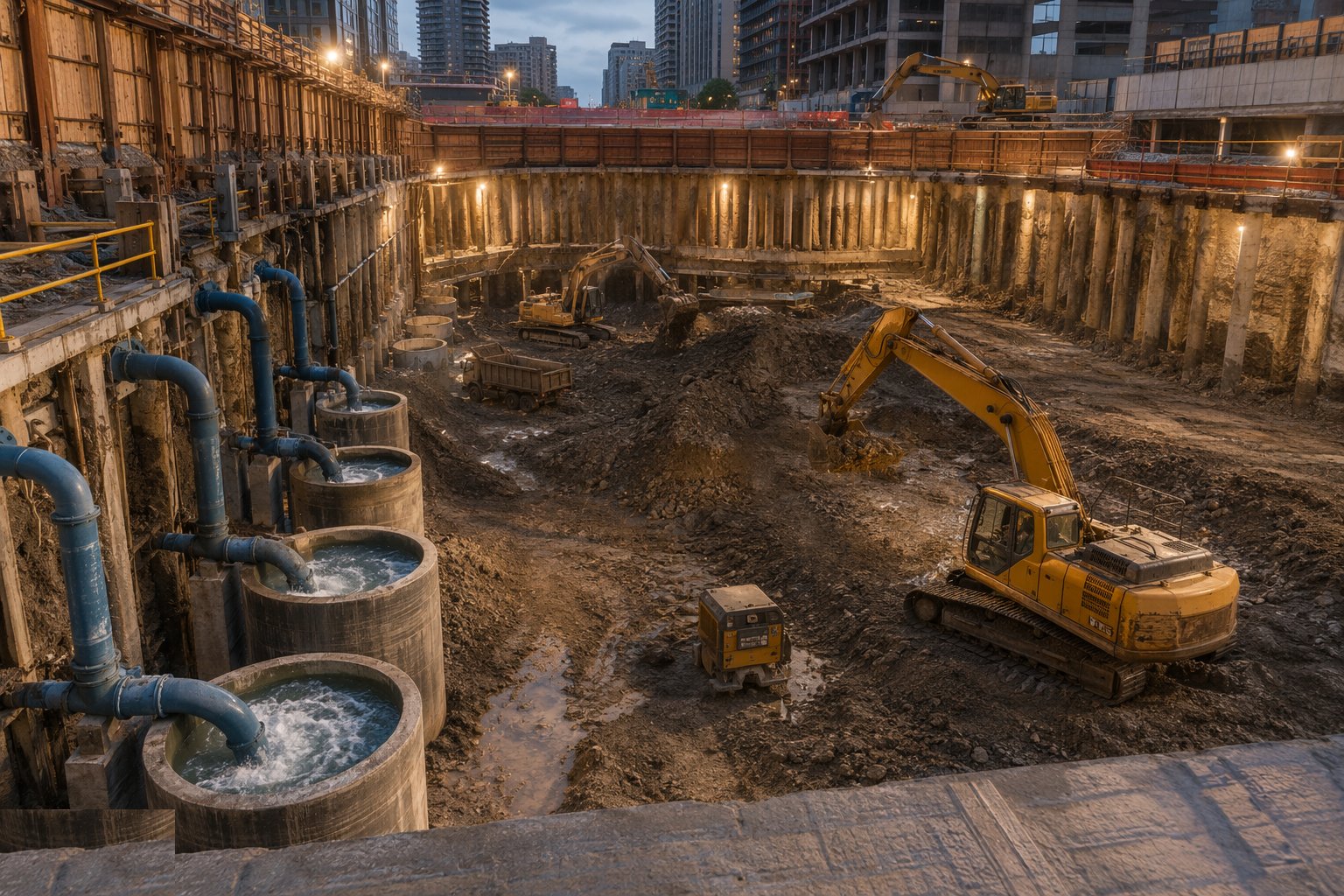
The cut-off approach stops fighting the water and excludes it: a physical barrier - driven sheet piles, a secant or contiguous piled wall, a diaphragm wall, or an injected grout curtain - is keyed into a low-permeability stratum below the dig, so groundwater cannot reach the excavation in quantity. Pumping volumes collapse from a torrent to a manage-able seepage, the drawdown cone barely reaches the boundary, and the neighbours' ground stays at its natural water level. Where the barrier doubles as the permanent basement wall, the economics can be compelling.
The catch is completeness. A cut-off that does not key into the impermeable layer leaks underneath - underdrainage - and the deeper the dig relative to the key, the worse the uplift and piping risk at the formation. Gaps between clutched sheet piles, a contaminated grout curtain, or a sand lens through the key stratum all let the water in at the worst place: the base, under pressure. The design therefore models seepage and base stability together, and the dig watches for boiling and heave with the same vigilance as any pumped scheme - a cut-off reduces the flow, it does not repeal the physics.
Recharge is the companion technique for the ground outside the wall - or for pumped schemes with no wall at all. Where drawdown would settle adjacent buildings, shrink clays or depress a protected water feature, clean water is injected back into the ground through recharge wells or trenches between the dig and the receptor, holding the water table up where it matters. It is water management with the neighbours' foundations in mind: consented, monitored, filtered water in, observation wells confirming the levels hold, and the whole arrangement documented for the party-wall and insurance files.
Process storyboard
Step 1 of 6 - slide through the snapshots.
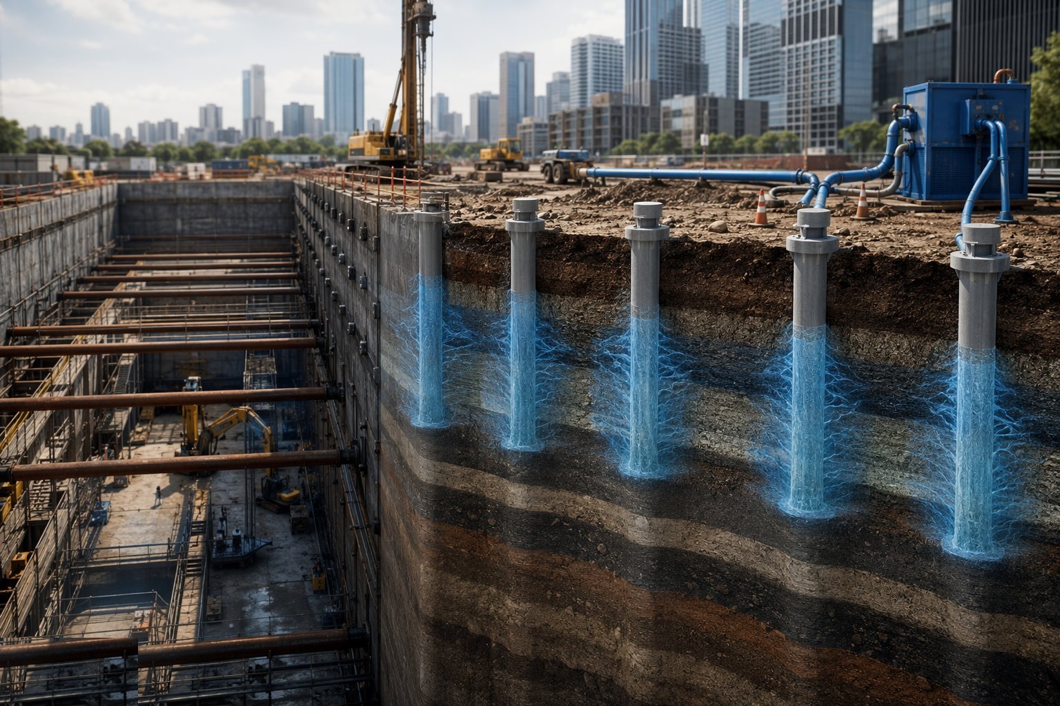
STEP 1
Establish the hydrogeology and the key stratum
The GI must identify the permeable horizons and, critically, the continuous low-permeability layer the cut-off will key into - its depth, thickness and…
How does Cut-off and recharge work, step by step?
- 1
Step 1: Establish the hydrogeology and the key stratum
The GI must identify the permeable horizons and, critically, the continuous low-permeability layer the cut-off will key into - its depth, thickness and continuity. Seepage modelling sizes the required embedment and predicts residual inflow and the external drawdown. Where external drawdown threatens receptors, the recharge requirement is designed at the same time, not discovered by a crack survey later.
- 2
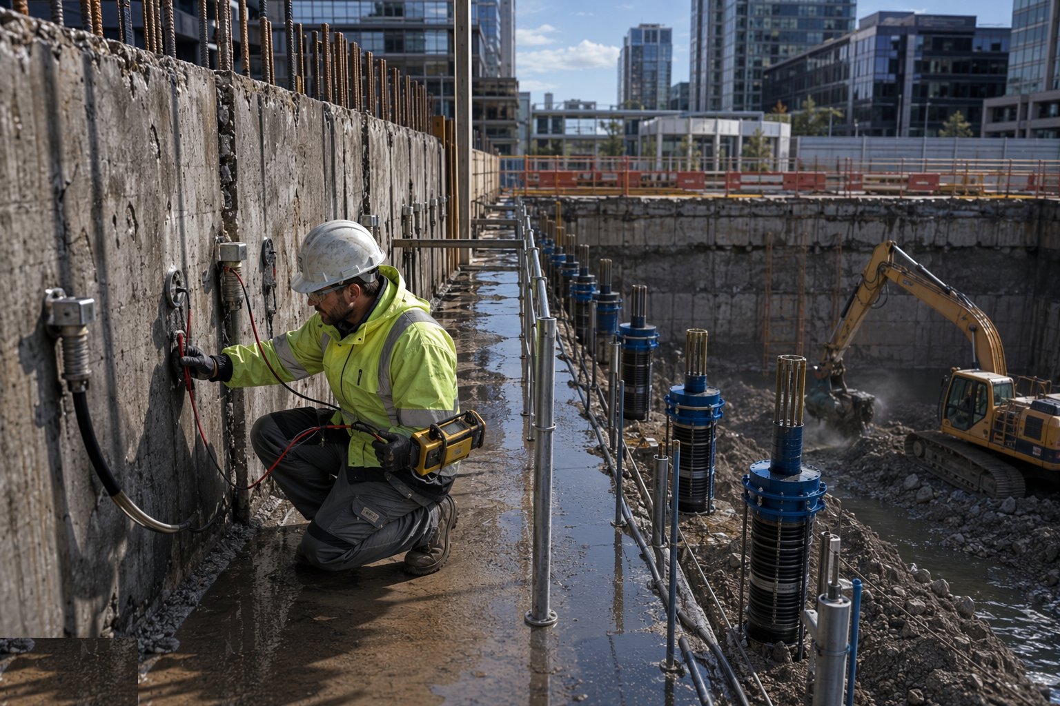
Step 2: Install the barrier and verify continuity
Sheet piles are driven with clutches interlocked and checked; piled walls are bored to overlap or secant as designed; grout curtains are injected to validated refusal criteria. Continuity is verified - pile logs, grout takes, water testing where specified - because the barrier is only as good as its worst joint. The key into the impermeable stratum is confirmed from the drilling or driving records against the GI.
- 3
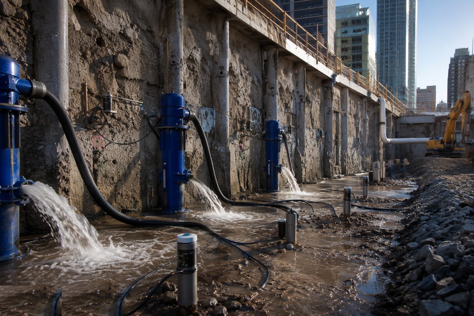
Step 3: Commission residual pumping and monitoring
A modest pumping system - sumps, a few wells - handles seepage through and under the barrier; it is sized from the seepage model, not guessed. Piezometers inside and outside the cut-off verify the water-level difference the design assumed. Observation wells between the dig and sensitive receptors go in before excavation, so there is a baseline to defend.
- 4
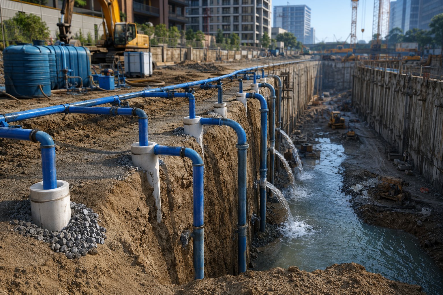
Step 4: Run the recharge system where required
Recharge wells or trenches are installed between the dewatered zone and the receptor, fed with water of acceptable quality - often the pumped discharge itself, treated and filtered, under the consent that allows it. Injection rates are balanced against observation-well levels: too little and drawdown continues, too much and water migrates where it is not wanted. The system runs for as long as the drawdown persists.
- 5
Step 5: Dig with base-stability vigilance
Excavation inside the cut-off proceeds with the formation watched for heave and piping - residual upward seepage under pressure is the cut-off's characteristic failure. The base-stability check from the design is revisited if actual water levels differ from prediction. Any boiling at formation stops the dig for reassessment; the response may be relief wells, a thicker blinding layer or a revised formation level.
- 6
Step 6: Close out against recovery and records
When the permanent works are complete and the flotation check is signed, pumping and recharge are stood down in sequence while water levels are monitored through recovery. Recharge and dewatering wells are grouted and abandoned to standard. The full file - design model, installation records, monitoring history, consents and close-out - is archived for the H&S file and any future neighbouring development.

What are the benefits of Cut-off and recharge?
- Slashes pumping volumes, energy and discharge consent burdens
- External drawdown nearly eliminated - neighbours' ground stays at natural water level
- Piled barriers can double as the permanent basement wall
- Recharge actively protects adjacent structures, trees and water features
- Predictable long-duration performance once installed
- Reduces fines migration and base instability compared with open pumping
What are the limitations of Cut-off and recharge?
- Requires a continuous impermeable stratum to key into - absent or deep, the method fails or costs dearly
- High upfront cost and installation time before any digging
- Underdrainage and base uplift remain - the physics is reduced, not repealed
- Recharge needs consents, water-quality control and constant balancing
- Sheet-pile driving brings noise and vibration to the very neighbours being protected
- Barrier defects are buried and expensive - a leaking clutch or grout gap shows only when the dig is deep
What is Cut-off and recharge best suited for?
What plant does Cut-off and recharge need?
- Sheet-piling rig with vibratory or pressing installation
- Piling rig for secant or contiguous walls, or diaphragm-wall grabs
- Grouting plant for curtain injection
- Recharge wells or trenches with filtration and injection pumps
- Piezometers, observation wells, data loggers and telemetry
- Residual pumping plant and silt control for seepage management
How is Cut-off and recharge quality-checked?
- Key-stratum continuity confirmed from installation records against the GI
- Barrier continuity verified - pile logs, clutch checks, grout takes
- Inside/outside piezometric difference verified against the design
- Recharge water quality and injection rates logged against consent
- Formation inspected for heave and piping at every stage of the dig
- Full monitoring and close-out file archived, with wells grouted on abandonment