Wellpoint systems
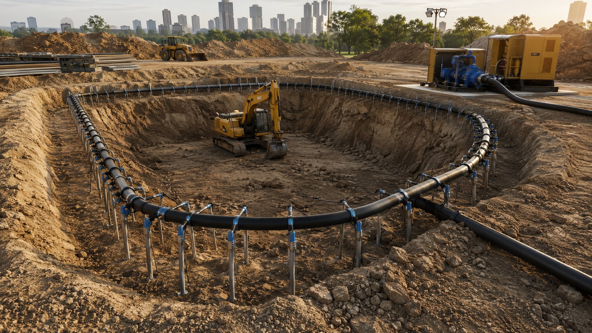
A ring of small wells on a vacuum header - draw the water down before the dig ever reaches it.
Last updated 2026-08-22
What is Wellpoint systems?
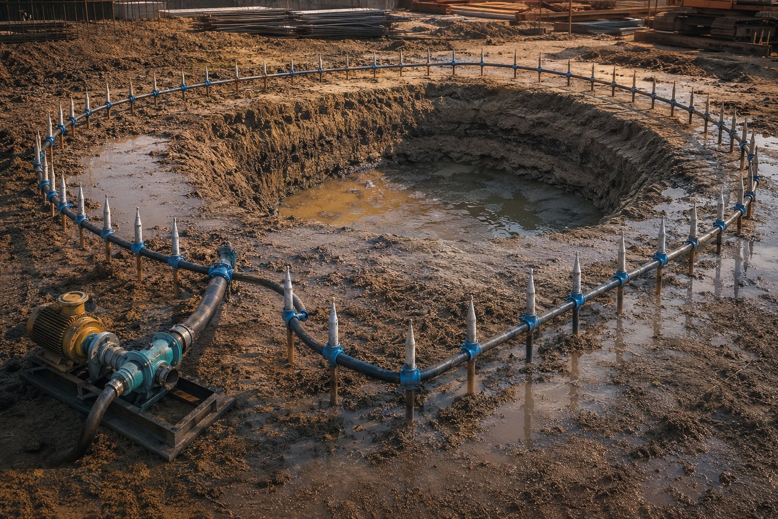
Wellpointing is the standard engineered answer to shallow groundwater in sands and gravels: a line of small-diameter wellpoints - screened tubes jetted or bored into the ground around the excavation - connected to a common header pipe and a vacuum-assisted pump. The system lowers the water table across the whole dig area before excavation arrives, so the ground is dug dry, stable and undisturbed. Suction physics limits each stage to roughly 4–5 m of drawdown; deeper digs use multiple stages on stepped berms, or graduate to deep wells.
The method works because it intercepts the water in the ground rather than fighting it in the hole. Properly designed and installed, the formation never sees flowing water: no fines migration, no boiling, no sides running in. The design comes from the GI - permeability, required drawdown, trench or excavation geometry - and sizes the wellpoint spacing, header layout and pump duty. The classic specification error is spacing points for the average ground and discovering the permeable lens the GI warned about at 2 a.m.
Wellpoints are a system, and they fail as a system. Air leaks at joints kill vacuum across the whole header; a blocked wellpoint silently stops contributing while its neighbours overload; fine silts clog screens and flows decay over weeks. The installation is tuned - valves per point, vacuum gauges watched, discharge checked - and the drawdown is proven in observation wells before the dig is trusted. The pump then runs 24/7 until the works are safe from flotation, because wellpoints that stop for a weekend hand the excavation back to the water table.
Process storyboard
Step 1 of 6 - slide through the snapshots.
STEP 1
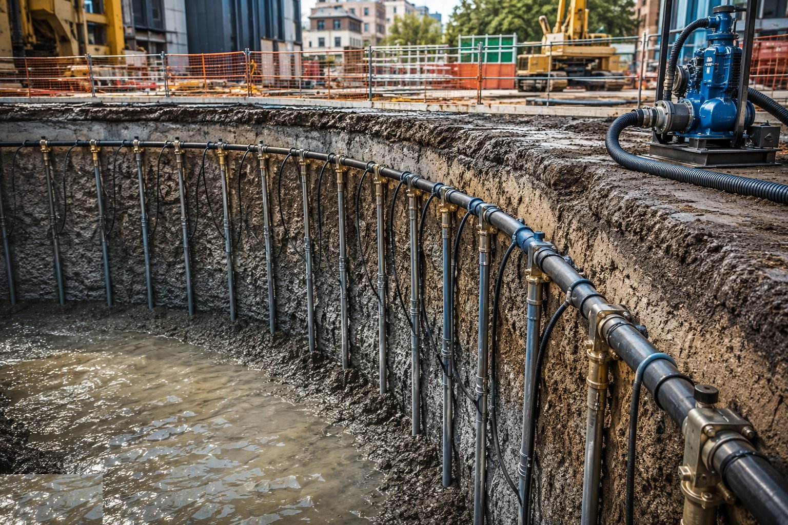
Design from the GI
Extract permeability, standing water level and seasonal variation from the ground investigation.
How does Wellpoint systems work, step by step?
- 1
Step 1: Design from the GI
Extract permeability, standing water level and seasonal variation from the ground investigation. Set the target drawdown - at least 0.5–1 m below formation - and compute flows to size wellpoint spacing (often 1–2 m in sands), header diameter and pump duty. Deep digs are staged: draw the section with berms and check the geometry of each suction lift against the 4–5 m limit.
- 2
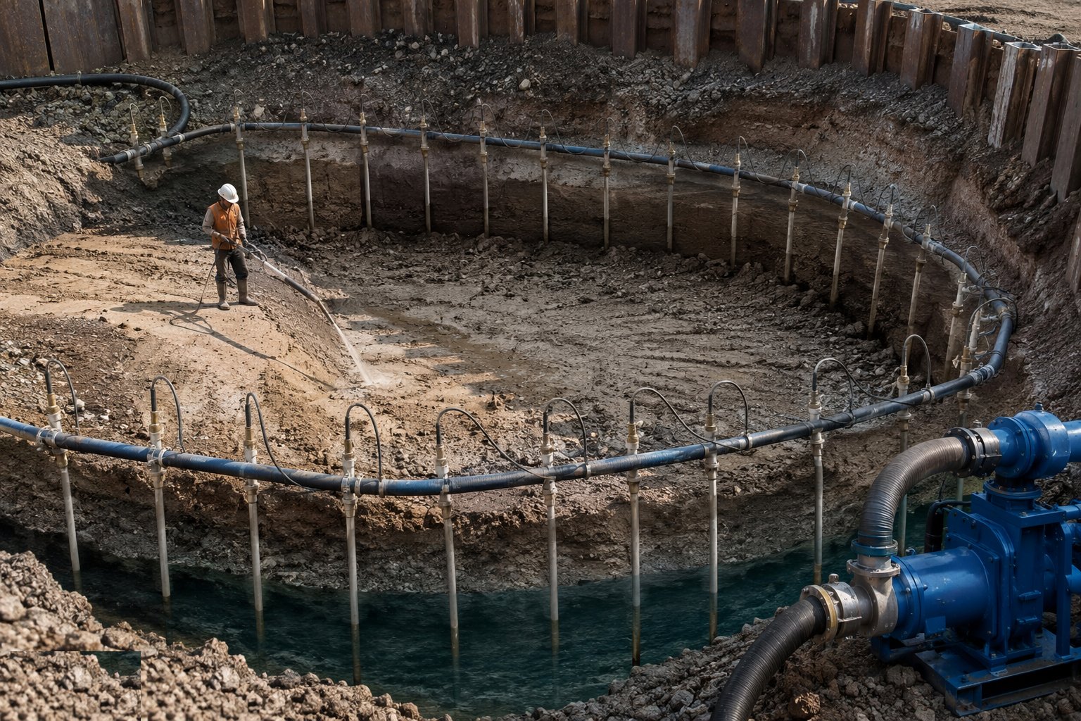
Step 2: Install the wellpoints
Points are jetted in with a high-pressure water lance or bored, the screen set at design depth, and the annulus sand-packed where the ground needs a filter - the sand pack is what stops the point pumping fines. Risers connect to the header with a valve per point so each can be tuned or isolated. In silty ground, installation quality decides whether the system works for weeks or clogs in days.
- 3
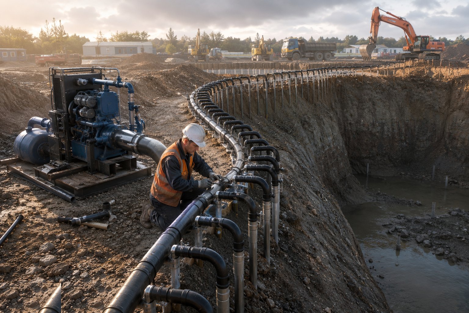
Step 3: Connect, seal and commission the header
The header ring is laid level around the dig, connected to the vacuum-assisted pump, and every joint checked - air leaks are the silent killer of vacuum systems. Commissioning is a tuning exercise: run up, watch the vacuum gauges, walk the line listening and feeling for leaks, and balance flows point by point. Discharge runs through silt control to the consented outfall.
- 4
Step 4: Prove drawdown before trusting it
Observation wells or dip tubes inside and outside the ring confirm the water level is actually falling to target - the pump running proves nothing except the pump. Digging proceeds only when monitoring shows drawdown at or beyond the requirement across the dig area. A point or zone lagging behind gets investigated: blocked screen, air leak or a permeability surprise.
- 5
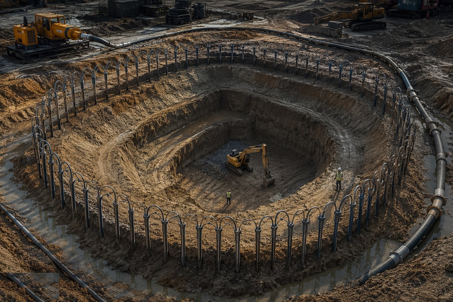
Step 5: Dig dry, in stages for deep excavations
Excavation proceeds inside the depressed water table, keeping formation comfortably above it. For staged systems, the first-stage ring runs while the dig forms the berm, then the second-stage header is installed on the berm and commissioned before digging on. Berms are cut and points relocated in the designed sequence - never dug away while still doing their job.
- 6
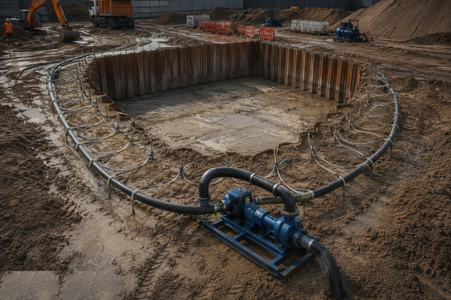
Step 6: Run continuously, then decommission in order
The system runs 24/7 with duty/standby changeover, alarms and weekend cover until the works resist flotation or are backfilled. Decommissioning reverses the logic: confirm the structure is safe, then pull points, grout or backfill the holes, close the discharge consent formally, and monitor recovery briefly to confirm it is benign for the neighbours.
What are the benefits of Wellpoint systems?
- Digs proceed dry and stable - no fines migration, no boiling formation
- Proven, modular and fast to install around trenches and shallow basements
- Drawdown is measurable and verifiable in observation wells
- Stages extend the method to 8–10 m of total drawdown on berms
- Cheap per metre of trench compared with deep wells or cut-offs
What are the limitations of Wellpoint systems?
- Suction limit of roughly 4–5 m per stage - deep digs need staging or deep wells
- Air leaks at any joint degrade the whole header
- Silts and fine sands clog screens - flows decay and points need redevelopment
- Low-permeability ground (clays, silts) responds poorly without vacuum enhancement or ejectors
- Must run continuously - a stopped system floods the dig within hours in permeable ground
- Drawdown can extend beyond the site - neighbours and consent conditions must be considered
What is Wellpoint systems best suited for?
What plant does Wellpoint systems need?
- Vacuum-assisted wellpoint pump sets (duty and standby)
- Wellpoints with screens, risers, valves and sand-pack material
- Header pipe, joints and vacuum gauges
- Jetting pump and lance or a small boring rig for installation
- Observation wells, dip tapes and data loggers
- Settlement tank or silt buster on the discharge
How is Wellpoint systems quality-checked?
- Design flow and spacing documented from GI permeability data
- Drawdown verified in observation wells before excavation reaches water
- Vacuum and flow logs reviewed daily; leaks and blocked points actioned
- Discharge quality checked against consent conditions
- Standby pump tested and changeover proven weekly
- Wellpoint holes grouted or backfilled and abandonment records filed