Deep wells and ejectors
Bored wells with their own pumps - drawdown measured in tens of metres, where suction cannot reach.
Last updated 2026-08-22
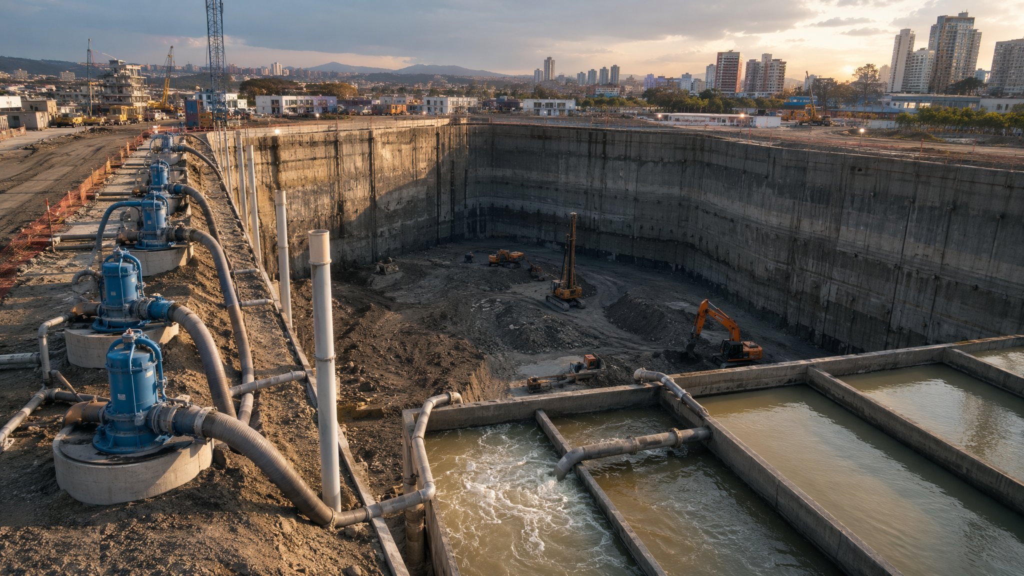
What is Deep wells and ejectors?
When the dig goes deeper than suction physics allows, the pump must go down the hole. Deep wells are bored wells - typically 150–300 mm diameter - drilled around or within the excavation, each fitted with a submersible pump that lifts water from depth and discharges it at surface. There is no 5 m limit: drawdowns of 20 m or more are routine, and wells can be spaced widely, placed outside the working area, and left running for months. For deep basements, shafts and major excavations in permeable ground, they are the default engineered solution.
Ejectors solve the opposite problem. In low-permeability ground - silts, silty sands, laminated soils - water moves so slowly that a submersible pump starves. An ejector system circulates high-pressure water down each well to a venturi nozzle that lifts groundwater back up a return line, applying a vacuum effect at depth; the whole loop runs off one surface pump station. Flows per well are small, but in tight ground small flows are all there are, and ejectors will pull water from ground that defeats both wellpoints and submersibles.
Both systems are designed assets with real consequences. Deep wells in high-permeability ground move serious volumes - discharge consents, silt control, energy and standby power all scale accordingly, and the drawdown cone can extend well beyond the boundary, putting neighbours' foundations and any sensitive receptors on the monitoring schedule. Wells are also obstructions: positioned badly they sit in the line of the works; abandoned badly they are vertical conduits for contamination. Installation records, grouting on decommissioning and the recovery-monitoring file are as much a part of the system as the pumps.
Process storyboard
Step 1 of 6 - slide through the snapshots.
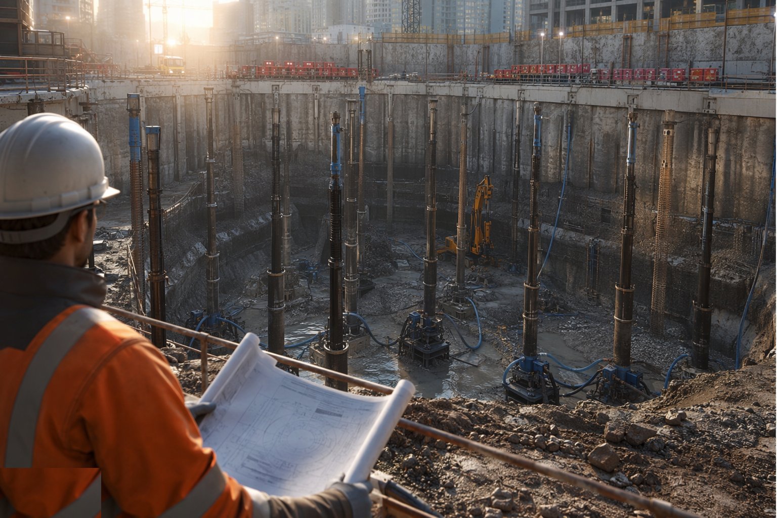
STEP 1
Design the array from pumping-test data
Deep dewatering is designed from real permeability - pumping tests or good GI data - not assumption.
How does Deep wells and ejectors work, step by step?
- 1
Step 1: Design the array from pumping-test data
Deep dewatering is designed from real permeability - pumping tests or good GI data - not assumption. The model sets well depth, screen position, spacing and pump duty to achieve target drawdown with margin, and predicts the drawdown cone beyond the site so monitoring and any recharge obligations are fixed up front. Ejector systems are chosen where permeability is low and suction lift is deep; submersibles where flows justify them.
- 2
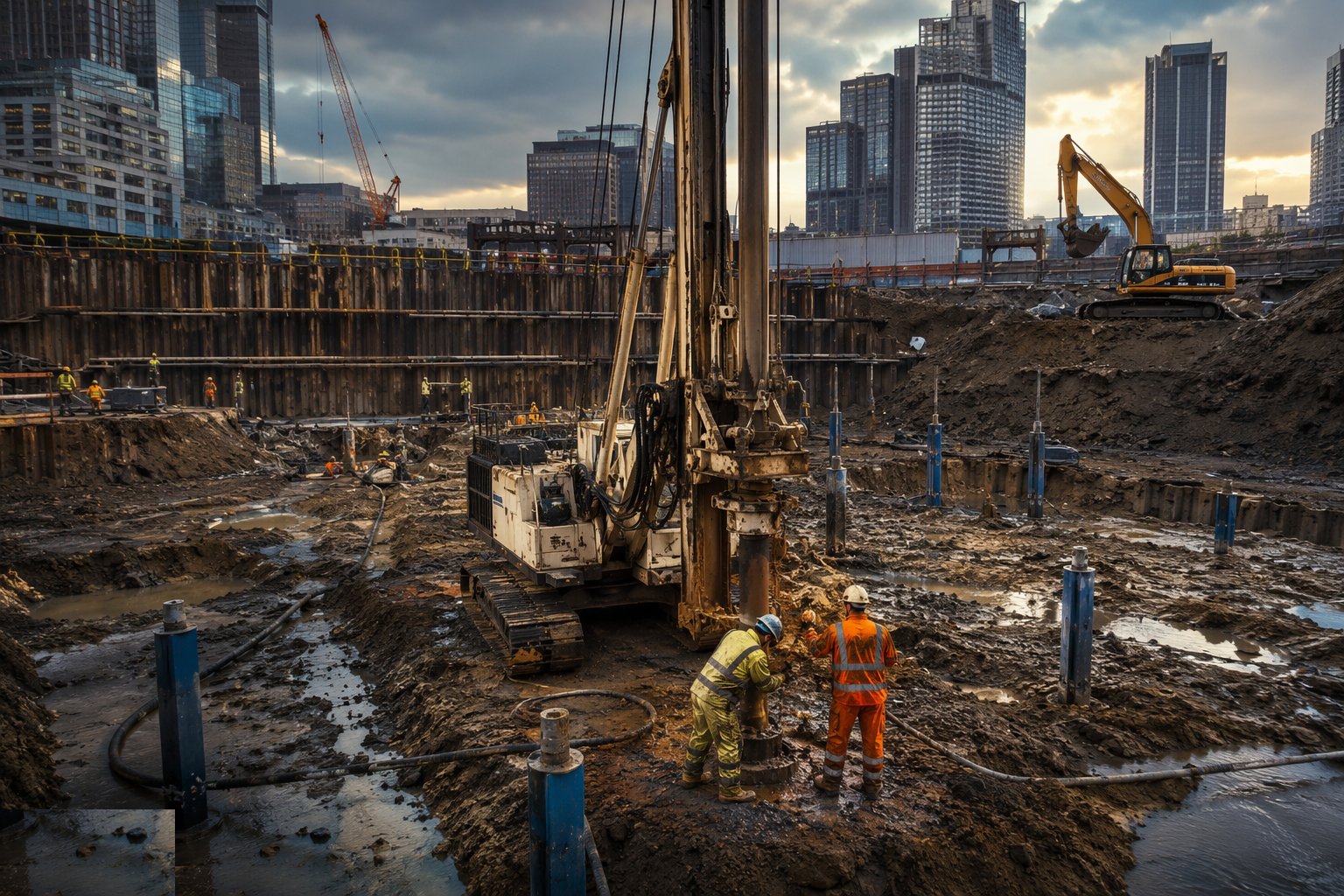
Step 2: Drill and complete the wells
Wells are drilled - rotary or cable-percussion - clear of the works' line where possible, cased and screened at the design horizons, and gravel-packed with a filter matched to the soil grading. Each well is developed on completion: pumped and surged until it runs clean, because a well that produces sand is eating the aquifer and itself. Flow and drawdown per well are recorded as the baseline.
- 3
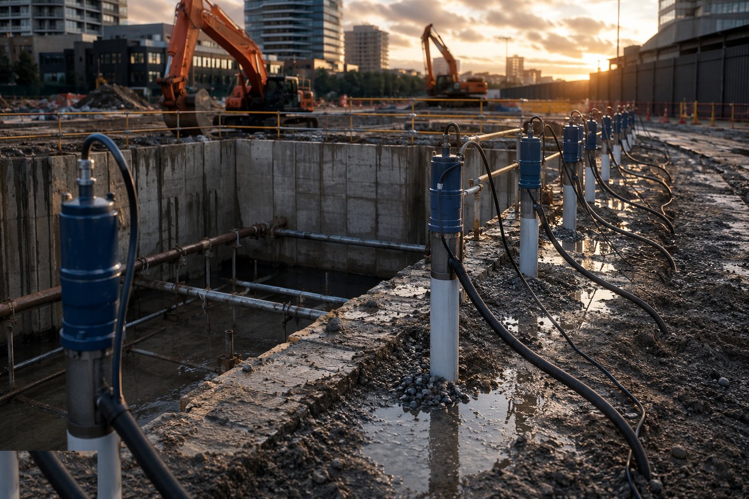
Step 3: Set pumps and commission the ring
Submersibles are set at design depth on rising mains to a common discharge manifold; ejectors are connected into their pressure and return ring mains from the surface station. The system is commissioned well by well - flows, levels and, for ejectors, supply pressures balanced across the array. Discharge runs through silt control sized for the full design flow to the consented outfall.
- 4
Step 4: Prove the drawdown curve
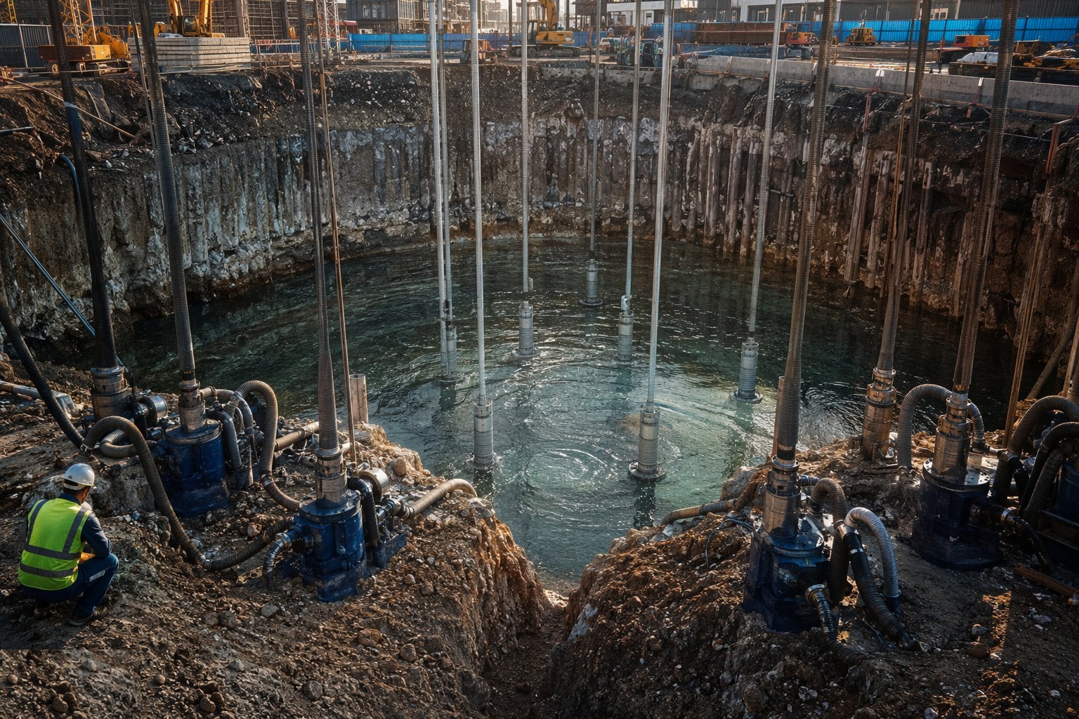
Observation wells inside and outside the array confirm the depressed water table matches the design curve before the dig is committed below water. Pumping is tuned - individual well duties adjusted - so drawdown is achieved without over-pumping, which wastes energy, pulls fines and spreads the cone unnecessarily. The dig then proceeds, staying inside the verified drawdown envelope.
- 5
Step 5: Monitor water, ground and neighbours
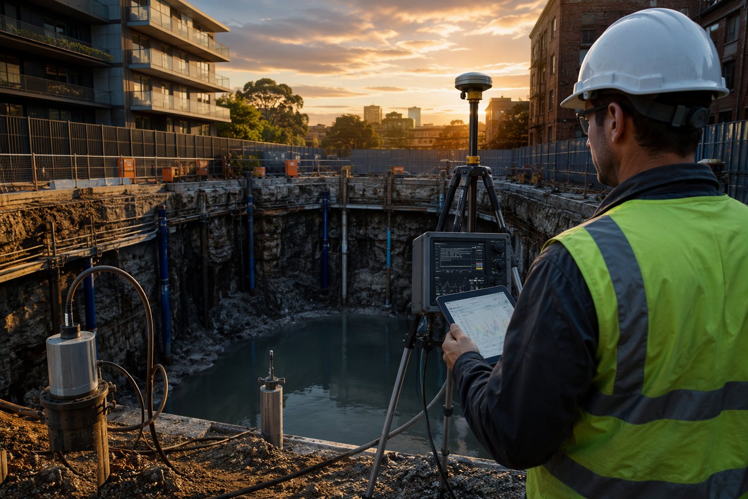
Water levels, flows and discharge quality are logged on programme; settlement points on adjacent ground and structures are read against trigger levels. A rising trend in the observation wells means a failing pump, a clogging screen or a seasonal rise - each with its own response, none of which is "wait and see". Wells are periodically redeveloped if flows decay.
- 6
Step 6: Decommission against the flotation check
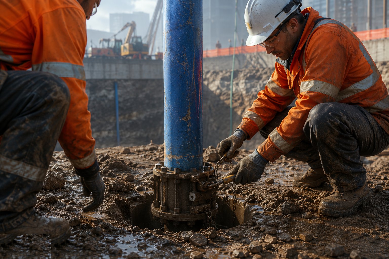
Pumping stops only when the permanent works carry the uplift - the flotation calculation is signed, backfill is placed, or the structure's weight is confirmed. Wells are then abandoned properly: pumps out, wells grouted or sealed to prevent vertical migration, records filed. Recovery of the water table is monitored briefly to confirm it is benign, and consents are formally closed.
What are the benefits of Deep wells and ejectors?
- Drawdown of tens of metres - no suction limit
- Wells can stand outside the excavation, clear of the works
- Handles high flows in permeable ground that would overwhelm wellpoints
- Ejectors dewater low-permeability silts nothing else will touch
- Months-long continuous duty with proper maintenance
- Predictable, modelled performance with verifiable monitoring
What are the limitations of Deep wells and ejectors?
- High cost per point - drilling, completion, pumps and months of power
- Wells are obstructions - badly positioned ones clash with the works
- Large drawdown cones risk neighbour settlement - monitoring and consents are mandatory
- Ejector flows are small - many wells needed for meaningful drawdown in tight ground
- Screens clog and pumps fail - continuous maintenance and standby are part of the deal
- Abandonment must be engineered - an open well is a contamination pathway
What is Deep wells and ejectors best suited for?
What plant does Deep wells and ejectors need?
- Drilling rig (rotary or cable percussion) for well installation
- Well casing, screens, gravel pack and grouting materials
- Submersible pumps with rising mains, or ejector bodies with ring mains
- Surface pump station for ejector systems
- Discharge manifold, settlement tanks and silt control sized for design flow
- Observation wells, piezometers, data loggers and telemetry
How is Deep wells and ejectors quality-checked?
- Pumping-test or GI permeability data filed with the design
- Well completion and development records per well - flows and baseline drawdown
- Drawdown verified against the design curve before digging below water
- Daily flow, level and discharge-quality logs; trends actioned
- Settlement and trigger-level monitoring at adjacent receptors
- Grouted abandonment records and recovery monitoring at close-out