Mechanical: ventilation and heating distribution
Ducts and pipework that own the ceiling void - gravity routes first, pressure and noise budgeted at every bend.
Last updated 2026-08-22
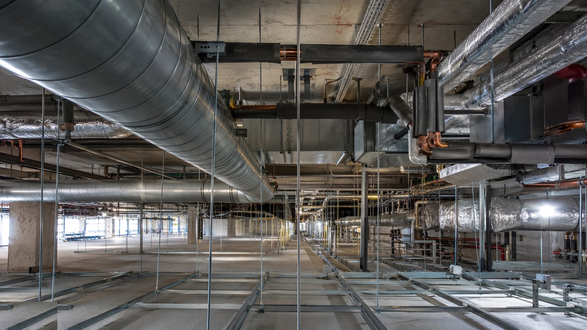
What is Mechanical: ventilation and heating distribution?
Of everything competing for the ceiling void, ductwork is the least flexible, so it wins coordination priority right after drainage falls. Rectangular and spiral-wound circular duct is fabricated to a recognised construction standard, joints sealed, hangers fixed to structure at rated centres. Every bend, transition and poorly made joint costs static pressure and generates noise - so routes are straightened at coordination stage, bends are radiused where space allows, and the fan duty in the design is defended like money, because it is.
Heating distribution is the other half of the mechanical scope: flow and return from the boiler, plant room or heat interface unit out to every emitter, in copper, press-fit or multilayer pipe. Runs get falls to drain points and air vents at high points; expansion is taken by changes of direction or formed loops, with anchors and guides where the design puts them. Chilled and cold services get vapour-sealed insulation - an unsealed joint in a ceiling void condenses quietly for months before the stain appears on someone's finished ceiling.
Both systems disappear at boarding, so both are proven first. Ductwork is leakage-tested to its pressure class where specified; pipework is hydraulically pressure-tested with the gauge witnessed and the result recorded; only then does insulation close over the joints. Every concealed run is photographed dimensioned to the grid lines, because the duct nobody can see is the duct the ceiling installer crushes, and the photograph file is the only map anyone will ever have.
Process storyboard
Step 1 of 6 - slide through the snapshots.
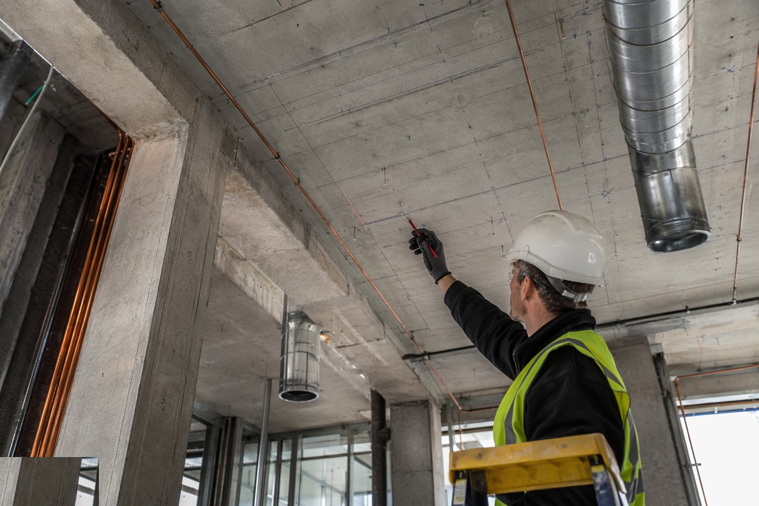
STEP 1
Set out from the coordinated ceiling plan
Mark the routes and hanger positions on the soffit from the coordinated drawing, checked against the structure as-built - a beam 50 mm off its drawn position…
How does Mechanical: ventilation and heating distribution work, step by step?
- 1
Step 1: Set out from the coordinated ceiling plan
Mark the routes and hanger positions on the soffit from the coordinated drawing, checked against the structure as-built - a beam 50 mm off its drawn position moves every service that crosses it. Duct levels are set from the site datum with the finished ceiling height protected; once a duct is hung low, no argument raises it again.
- 2
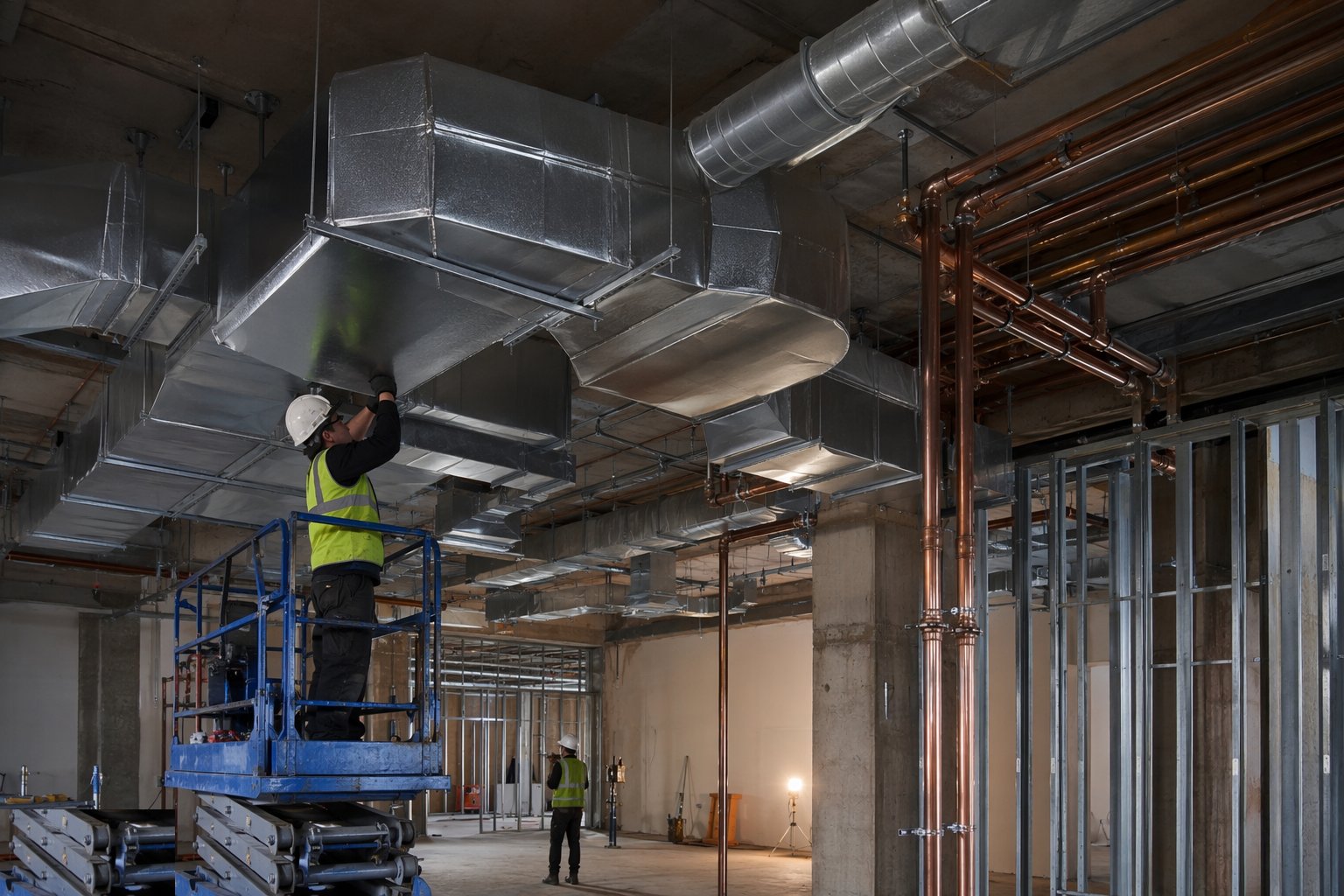
Step 2: Fabricate and hang the ductwork
Sections are assembled with sealed joints to the construction standard and hung from structure on threaded rod at rated centres - never from other services, never from the ceiling grid. Flexible connections at fans keep vibration out of the duct run, and long runs get the cross-joints and stiffening the standard demands for their pressure class.
- 3
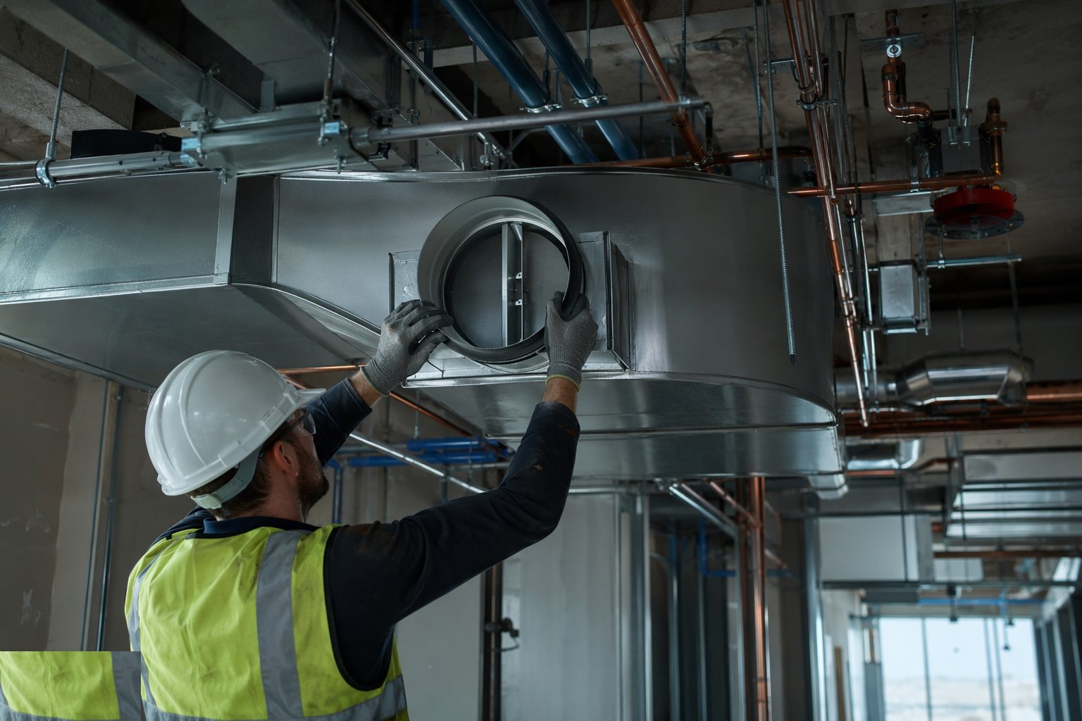
Step 3: Install dampers, access and fire interfaces
Volume control dampers go where the balancing engineer can reach them after the ceiling is up. Fire dampers at compartment lines are installed to the manufacturer's tested detail - correct substrate, correct fixing, access panel alongside - because a damper fixed to the wrong construction has no rating at all.
- 4
Step 4: Run the heating and chilled pipework
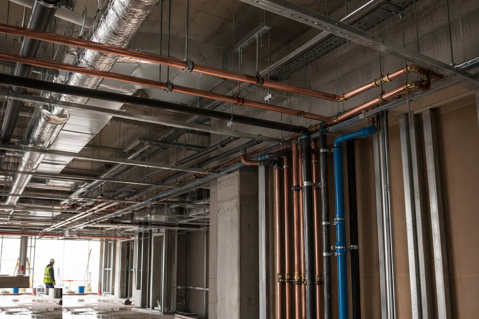
Flow and return are run with falls to drain points and vents at the high spots, sleeved through walls, and bracketed at designed centres with expansion accommodated by route or loop. Terminal tails to emitters are set from the finishes drawings - a pipe 30 mm off becomes an exposed offset after tiling.
- 5
Step 5: Test before anything closes
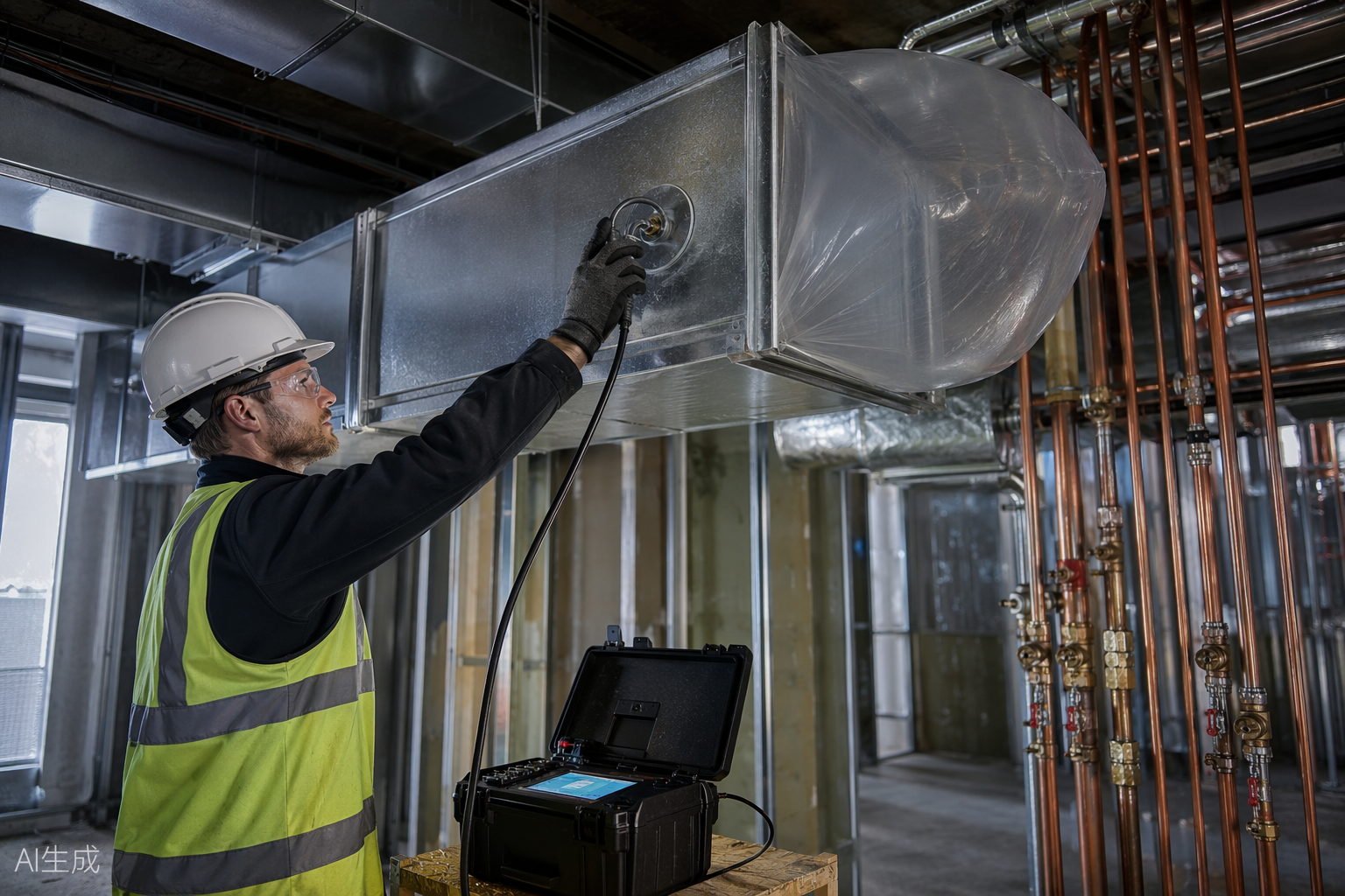
Ductwork is leakage-tested against its specified pressure class, section by section. Pipework is hydraulically tested, held at test pressure with the gauge reading witnessed and recorded. A joint that weeps under test is remade now; a joint that weeps after boarding is a ceiling-down repair.
- 6
Step 6: Insulate, identify and record
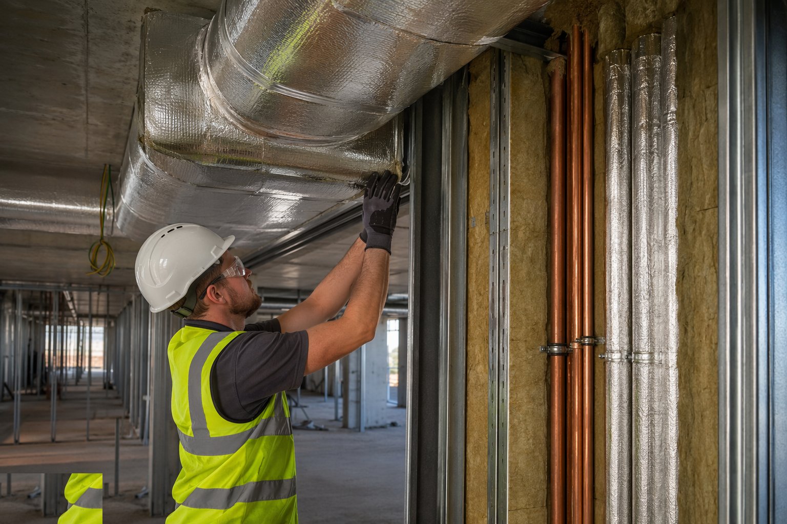
Insulation goes on over proven joints, vapour-sealed on cold services with every butt and penetration closed. Flow arrows, valve tags and service labels identify the runs, the as-installed markup is updated, and dimensioned photographs of every concealed run are filed against the grid lines before the boarders arrive.
What are the benefits of Mechanical: ventilation and heating distribution?
- Engineered airflow - sealed, straight-routed ductwork delivers the design rates quietly
- Distribution sized for the load - balanced systems run efficiently from the day they are filled
- Accessible maintenance - dampers, valves and drains positioned to be reached after closure
- Fire integrity maintained - tested fire damper details keep the compartment lines intact
- Headroom protected - ducts installed to coordinated levels keep the ceiling height as designed
What are the limitations of Mechanical: ventilation and heating distribution?
- Space-hungry - ductwork drives ceiling depths and riser sizes; late coordination costs headroom
- Bends and leakage eat fan duty - poor routing means noise and under-performing ventilation
- Committed early - late emitter or layout changes mean drain-downs, re-runs and rework
- Insulation defects are invisible after closure - condensation damage surfaces months later
- Fire damper installation is detail-critical - the wrong fixing or substrate voids the rating
What is Mechanical: ventilation and heating distribution best suited for?
What plant does Mechanical: ventilation and heating distribution need?
- Duct fabrication kit: folders, seam closers, spiral and rectangular stock
- Pipe press-fit, threading and soldering equipment
- MEWPs, podiums and towers for high-level installation
- Duct leakage test rig and pressure test pumps with calibrated gauges
- Laser levels and datum kit for setting out
- Insulation tools: knives, foil tapes, vapour-seal adhesives
How is Mechanical: ventilation and heating distribution quality-checked?
- Duct leakage test certificates against the specified pressure class
- Pipework pressure test records - pressure, duration, witness, result
- Fire damper installations checked against the tested detail and photographed
- Hanger and support centres verified against the construction standard
- Insulation continuity and vapour-seal inspection before closure
- Dimensioned photographs of every concealed run filed against grid lines
More mep first fix methods
Next method
Electrical: containment and wiring