Ventilation and controls
Grilles set to design flow, controls proven point by point - where energy performance is actually delivered.
Last updated 2026-08-22

What is Ventilation and controls?
Ventilation second fix fits the visible ends of the air systems: grilles, valves and diffusers set to their design positions, MVHR and fan units connected with condensate drains proven, extracts commissioned dwelling by dwelling. Compliance here is measured, not assumed - the ventilation rates are read at each terminal with a balometer or anemometer and set to the design figures, because an extract fan achieving half its duty is a mould problem with a five-year fuse.
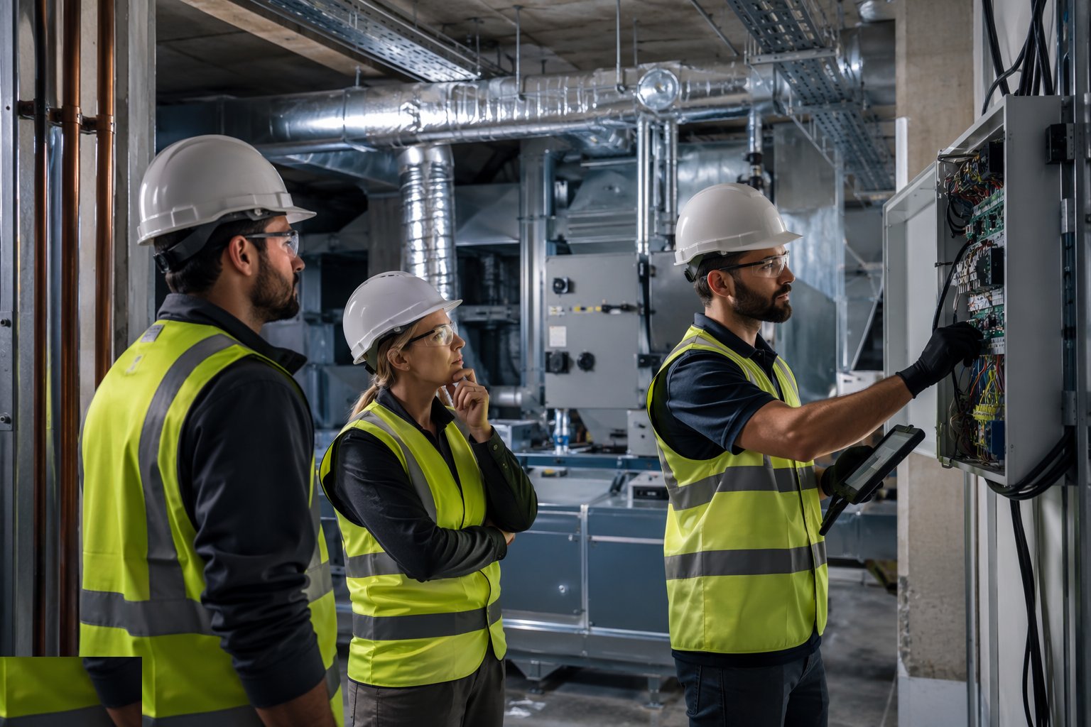
Controls are where the building's intelligence lives: thermostats, programmers, radiator valves and smart controls in dwellings; on larger buildings, the BMS - every sensor and actuator landed, addressed and proven point to point from the field device to the controller before any software is configured. Time schedules, setpoints, interlocks and alarms are set against the control strategy, and this is where the energy performance promised at design is either delivered or quietly abandoned.
Balancing ties it together. Air is measured and set terminal by terminal; the water side is balanced so each emitter gets its design flow; the figures are recorded against the design values, terminal by terminal, radiator by radiator. Commissioning time is the first thing a squeezed programme cuts and the costliest to recover - an uncommissioned building is an untested hypothesis with curtains. Seasonal return visits, in real heating and cooling weather, are where the fine performance is actually achieved.
Process storyboard
Step 1 of 6 - slide through the snapshots.
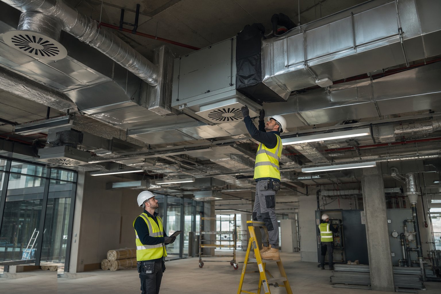
STEP 1
Fit the terminals and units
Grilles and diffusers are fitted to the ductwork at their design positions; MVHR and fan units are connected and the condensate drains proven with water.
How does Ventilation and controls work, step by step?
- 1
Step 1: Fit the terminals and units
Grilles and diffusers are fitted to the ductwork at their design positions; MVHR and fan units are connected and the condensate drains proven with water. Terminals moved for convenience change the measured picture - moves go through the designer, not the fitter.
- 2
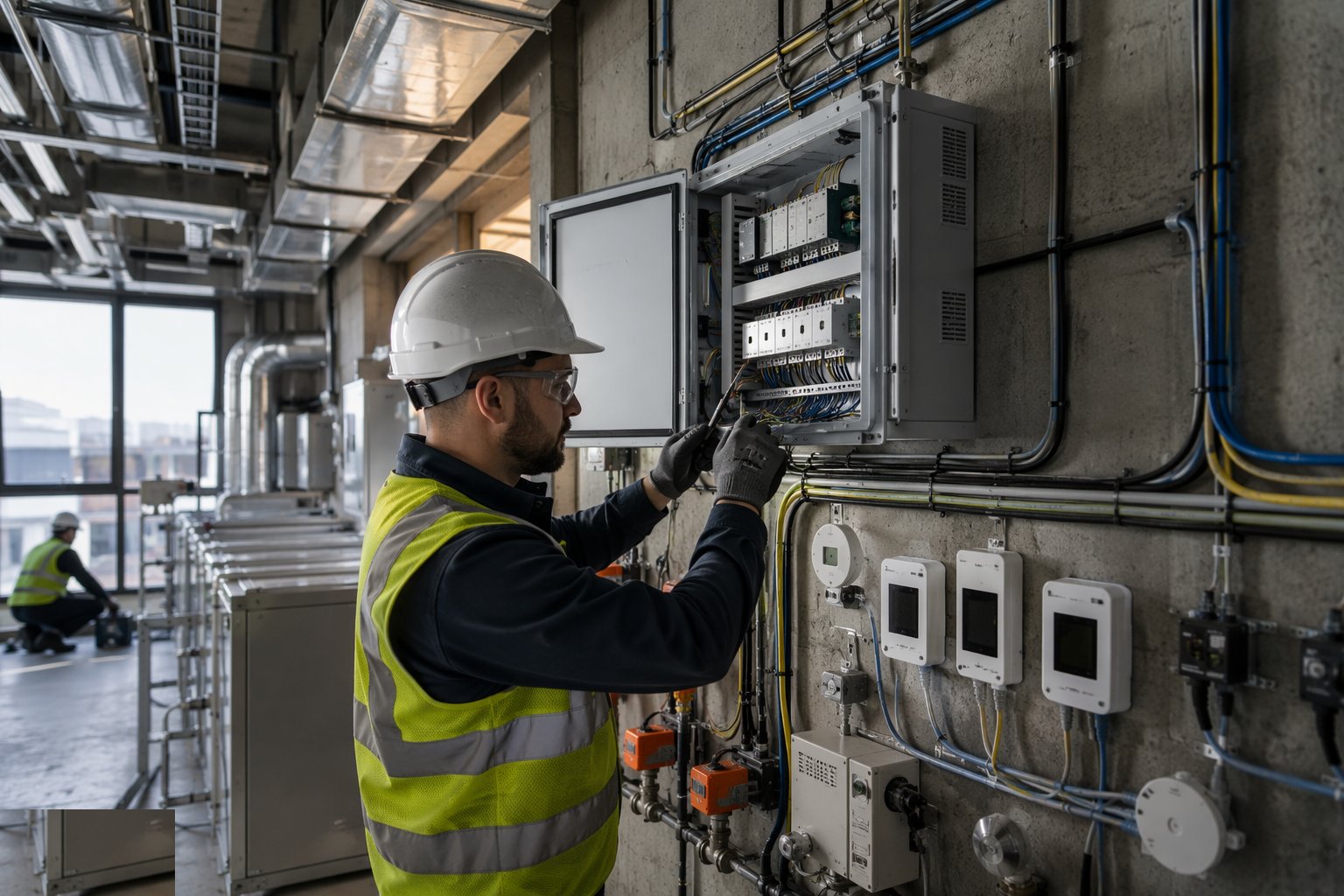
Step 2: Land the control wiring
Sensors, thermostats and actuators are wired and BMS points terminated against the points schedule. Every cable is identified at both ends - the point-to-point checks that follow depend on it.
- 3
Step 3: Prove every point
Point-to-point checks run from each field device to the controller: the sensor reads, the valve strokes, the fan status reports. One hundred percent complete before software configuration begins - graphics built on unproven points are decoration.
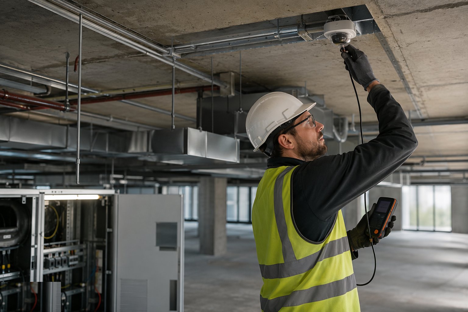
- 4
Step 4: Balance the air
Flow is measured at every grille with a balometer or anemometer and set to the design figure, terminal by terminal, with the results recorded. Leaky ducts and crushed flexible connections are found here, by the numbers, not by complaint.
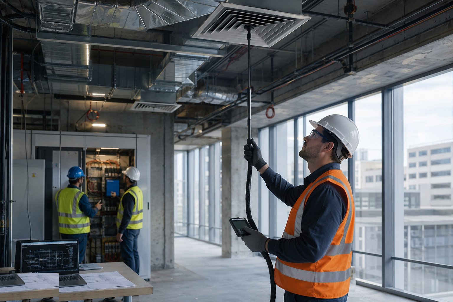
- 5
Step 5: Configure the controls
Schedules, setpoints, interlocks and alarms are configured against the control strategy and the cause-and-effect matrix. Graphics, trends and alarms are verified against the physical plant they claim to represent.

- 6
Step 6: Witness, record and tune
Demonstrations are witnessed by the client or commissioning manager and signed; balancing records and check sheets are filed. Seasonal commissioning visits are scheduled in the handover plan - real weather is the final examiner.
What are the benefits of Ventilation and controls?
- Compliance by measurement - ventilation rates proven at every terminal, not assumed
- Energy performance delivered - commissioned controls stop plant fighting itself
- Comfort and quiet - balanced air removes draughts, noise and stuffy rooms
- Meaningful alarms - proven BMS points make every alarm worth acting on
- Defensible handover - balancing records and point-to-point sheets are contractual evidence
What are the limitations of Ventilation and controls?
- Commissioning time is the first thing squeezed - and the costliest to recover
- Air balancing depends on the build - leaky ducts and crushed flexibles defeat the numbers
- Controls competence is scarce - BMS engineers are a programme bottleneck on every job
- Setpoints drift - without seasonal tuning and an engaged operator, the savings evaporate
- Terminal positions get value-engineered - moved grilles change the measured picture
What is Ventilation and controls best suited for?
What plant does Ventilation and controls need?
- Balometers, anemometers and vane kits
- BMS laptops, addressing tools and interfaces
- Multimeters and commissioning spares
- Temperature and humidity logging kit
- Access equipment for high-level terminals
- Calibration certificates for every measurement instrument
How is Ventilation and controls quality-checked?
- Measured flow rates recorded at every grille against the design figures
- BMS point-to-point check sheets 100% complete before configuration
- Control strategy, schedules and setpoints documented and witnessed
- Condensate drains proven on every unit
- Witnessed demonstrations signed by the client or commissioning manager
- Seasonal commissioning visits scheduled and logged in the handover plan