Piled lines for boiler, stack, racks and transformers
The long lines of foundations serving the rest of the plant, where accuracy across the whole site decides whether the delivered steel fits.
Last updated 2026-09-07
What is Piled lines for boiler, stack, racks and transformers?
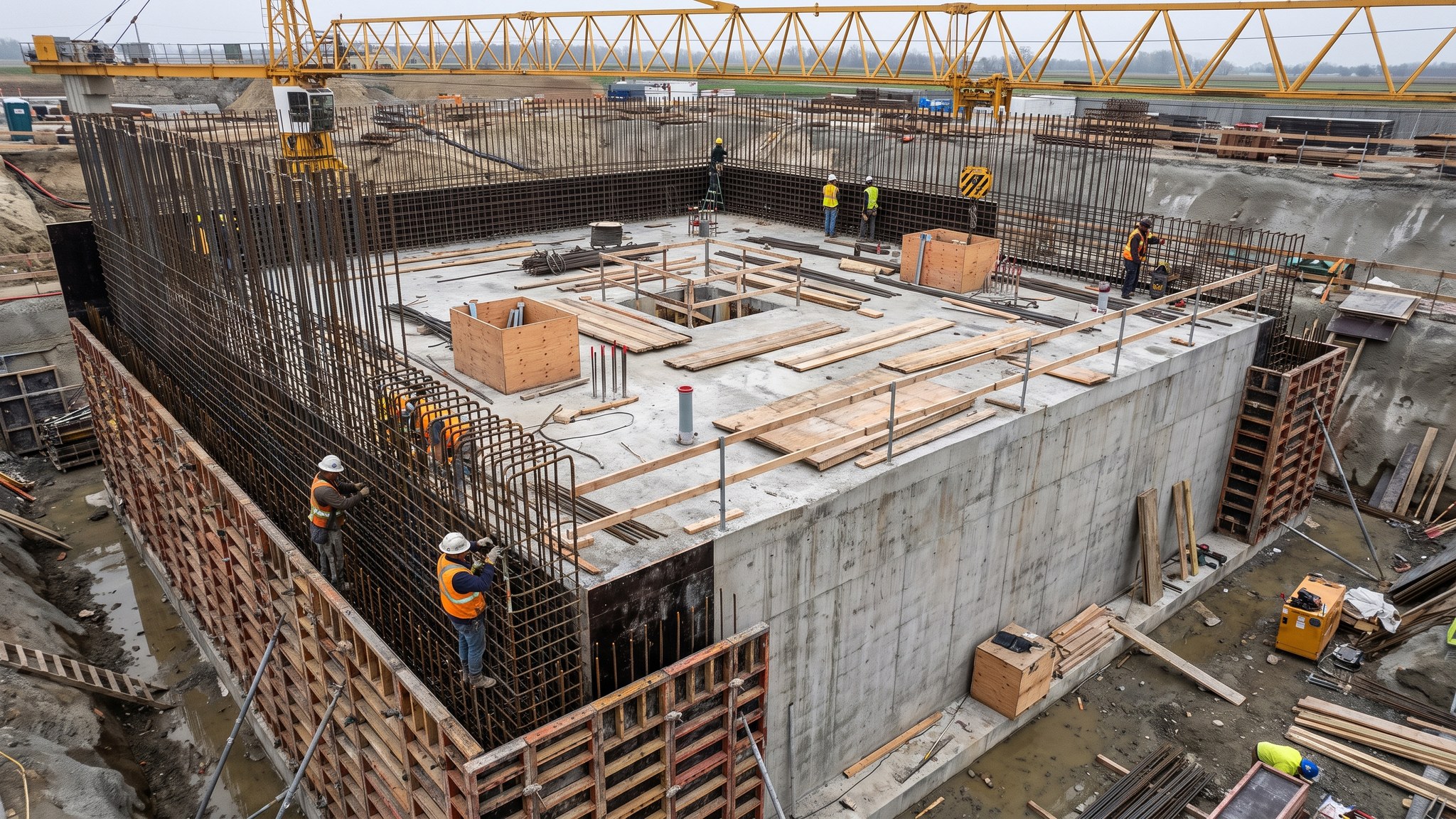
Beyond the machine block, a thermal power project is a landscape of foundations: the boiler or heat recovery unit, the stack, the air-cooled or water-cooled heat rejection equipment, the transformer bases and their bunds, and the long pipe racks and cable routes that tie everything together. Where the ground will not carry them, they are piled. Individually none of these is as demanding as the turbine block. Collectively they are harder, because there are hundreds of them, they are spread across the whole site, and they all have to line up with steelwork and modules that are being fabricated somewhere else at the same time.
Setting-out accuracy across the site is the governing issue. A pipe rack is a repeated frame delivered in long pieces; a boiler structure is a tall assembly of columns landing on a grid; transformer bases carry equipment with fixed footprints and fixed connection points. All of it is made to the drawing and none of it is adjustable on arrival by more than a very small amount. If the site control network drifts, or if different gangs work from different marks, the foundations will be individually within tolerance and collectively wrong, and the error only appears when the steel is hanging from a crane. Establishing one control network, protecting it and checking it is therefore the single most valuable thing the civils team does.
The second theme is that each family of foundations has its own requirements layered on top. Transformer bases usually sit within bunds and involve fire separation, oil containment and drainage that have to be built as one system rather than added afterwards. Stacks are tall and slender, so their foundations are dominated by wind and overturning rather than by weight. Boiler and heat recovery structures come with their own supplier interface information and their own embedded items. Pipe racks are simple but numerous, and the productivity of installing them is what drives the programme. The civils team is really running several small campaigns at once, which is why the sequencing and the delivery dates set by the equipment suppliers dominate the plan.
How does Piled lines for boiler, stack, racks and transformers work, step by step?
- 1
Step 1: Establish one site-wide survey control network
A single primary control network is set out across the whole site, monumented on stable ground, positioned clear of the works and of construction traffic, and adjusted as a whole. Every gang, every subcontractor and every setting-out engineer works from it. It is re-checked at regular intervals through the project and after any disturbance. Secondary control is established from it rather than from previous setting-out. This is dull work and it is the reason delivered steel fits.
- 2
Step 2: Gather the equipment supplier interfaces before designing
The boiler or heat recovery supplier, the transformer supplier, the heat rejection supplier and the rack designer each issue loads, base plate arrangements, bolt patterns and tolerances. The foundation design follows those interfaces, and the design is not frozen until they are received. Late changes to a supplier package ripple straight into the foundations, so the interface register is tracked actively and the civils programme is built around the dates the information is due rather than the dates the concrete is wanted.
- 3
Step 3: Design and lay out the piles for each family of structures
Pile type, length and layout follow the ground and the loading, and the loading differs sharply between families. Stacks are dominated by overturning and need a foundation that resists it. Boiler and heat recovery structures bring heavy concentrated column loads. Transformers are heavy but comparatively compact. Pipe racks are light but repeated over long distances. The designer produces a coherent scheme across all of them, and the contractor plans the pile installation as a campaign that moves logically across the site rather than jumping to wherever the crane happens to be.
- 4
Step 4: Install and test the piles as a managed campaign
Piles are installed in a planned sequence, with the rig moving along the lines so that access, spoil handling and concrete supply stay efficient. Records are kept pile by pile - position, depth, and the parameters the specification requires. Testing follows the agreed regime, with integrity testing across the population and load testing on selected piles. Positional tolerance is checked as work proceeds, because a pile out of position is dealt with by the designer through the cap, and that is far cheaper to resolve at the time than after the cap is designed.
- 5
Step 5: Break down, cast the caps and set the holding-down assemblies
Pile heads are broken down to level, reinforcement is cleaned, and caps and plinths are cast. Holding-down bolt assemblies are set on rigid independent frames to the supplier's bolt pattern and surveyed before the pour. Where a supplier provides templates they are used. Every plinth is surveyed after casting and the results are compiled into a single as-built model of the whole site, not held as separate sheets, because it is the relationship between plinths that the incoming steel cares about.
- 6
Step 6: Build the transformer bases and their containment as one system
Transformer foundations are rarely just a base. They typically sit inside a bund, with oil containment, interceptors, drainage, fire separation walls and cable routes forming part of the same construction. The containment has to be built and proved as an integrated system, with penetrations sealed and falls correct, because retrofitting containment around an installed transformer is close to impossible. Access for delivering and positioning the transformer is planned before the base is built, not after.
- 7
Step 7: Build the racks and route the underground services with them
Pipe rack and cable route foundations are repetitive, which makes them ideal for a production approach: one gang, one method, moving continuously along the line. Underground drainage, ducts, earthing and firefighting mains generally share the same corridors, so they are installed in a coordinated sequence with the foundations rather than being dug back in later. Backfill and reinstatement follow immediately, so the corridor is handed over complete and trafficable.
- 8
Step 8: Compile the as-built survey and hand over to erection
Before steel and modules arrive, the as-built survey of every plinth and holding-down assembly is compiled and compared against the fabricator's dimensional control. Any discrepancy is resolved with the designer and the supplier while it is still a drawing problem. Foundations are then cleaned, threads protected, pockets covered and access routes confirmed, so that erection can start on the agreed date with no remedial work at the front of it.
What are the benefits of Piled lines for boiler, stack, racks and transformers?
- Provides reliable support for heavy and tall plant where the ground alone will not do
- Repetitive foundations suit a production approach that is quick once the campaign is running
- Piling can be phased across the site so that early areas are handed over while later ones continue
- Consistent site-wide control gives incoming steel and modules a good chance of fitting first time
- Allows underground services to be installed in the same corridors and sequence as the foundations
- Keeps settlement small and predictable under equipment that is sensitive to movement
What are the limitations of Piled lines for boiler, stack, racks and transformers?
- Setting-out errors accumulate across a large site and are only discovered when steel arrives
- Design cannot be completed until every equipment supplier has issued its interface information
- Hundreds of separate foundations mean a heavy inspection, survey and record-keeping load
- Transformer containment and fire separation add complexity that cannot be retrofitted
- Pile installation across a live construction site conflicts with other trades for access and craneage
- Late supplier changes translate directly into abortive or reworked foundations
What is Piled lines for boiler, stack, racks and transformers best suited for?
What plant does Piled lines for boiler, stack, racks and transformers need?
- Piling rigs suited to the pile type, with service cranes and spoil handling plant
- Pile testing equipment for integrity and load testing across the campaign
- Excavators, breakers and croppers for pile head break-down
- Concrete supply and placing plant for a long run of small to medium pours
- Mobile cranes for cages, formwork, containment elements and templates
- Total stations and site-wide monumented control, with data compiled into a single as-built model
How is Piled lines for boiler, stack, racks and transformers quality-checked?
- Single primary control network established, monumented and re-checked at agreed intervals
- Equipment supplier interface information logged, tracked and confirmed before design freeze
- Pile records and testing results completed and accepted before caps are cast
- Holding-down assemblies set on independent frames, surveyed pre-pour and post-pour
- Transformer containment proved as a system, with falls, seals and interceptors verified
- Site-wide as-built survey compiled and reconciled against fabrication dimensional control before erection