Piled turbine-generator block
A massive reinforced concrete block on piles carrying the machine, where how it moves matters more than how much it weighs.
Last updated 2026-09-07
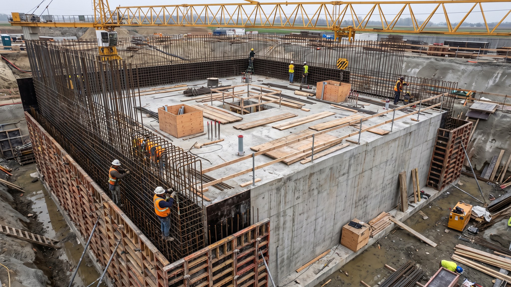
What is Piled turbine-generator block?
The turbine-generator block is the single most important piece of civils on a thermal power project. It is a large reinforced concrete structure, commonly a table or a solid pedestal, founded on piles and carrying the turbine, the generator and the shaft line that connects them. On most projects it is heavily reinforced, thick in every direction, and cast with embedded plates, pockets, sleeves and holding-down assemblies that belong to the turbine supplier rather than to the civils designer. It looks like a simple lump of concrete on a drawing. It is not. It is a machine foundation, and it is designed and built to a different standard of care from everything else on the site.
The governing design issue is dynamic behaviour, not static load. The machine is heavy, but the weight on its own is rarely the difficulty - the difficulty is that the shaft turns continuously at high speed for years, and the block has to sit clear of the frequencies that the rotating machine excites. It also has to stay stiff and stable under the out-of-balance forces that arise as bearings wear, as blades foul or as the machine trips, and it has to keep the shaft line aligned across its whole length while the concrete creeps, shrinks and warms. The turbine supplier states what the foundation must achieve and the designer produces a structure that meets it. That relationship is fixed from the start of the project and every civils decision after it follows from the supplier's requirements.
Building it is an exercise in accuracy under a very heavy reinforcement cage. The supplier's tolerances on embedded items are punishing - far tighter than anything else the concrete gang will meet on the project - and a plate set out of position is not something that can be argued away later, because the machine will not fit. Most teams therefore treat the block as its own mini project, with its own setting-out control, its own survey team, its own inspection regime and its own programme float. The block also sits on the critical path in a very literal way: the turbine cannot be set until the block is cast, cured and surveyed, and the plant cannot be commissioned until the turbine is set.
How does Piled turbine-generator block work, step by step?
- 1
Step 1: Take the turbine supplier's foundation requirements as the brief
Nothing sensible can be drawn until the turbine supplier issues the foundation loading and interface information. That package typically covers the machine weights and their positions, the operating and fault conditions the foundation has to carry, the behaviour the supplier expects of the structure, the layout of every embedded item, and the tolerances that apply to them. The designer works to that brief. On most projects the supplier reviews and comments on the resulting design, and the civils cannot be frozen until that loop is closed. Where the supplier is not yet appointed, the designer works to an assumed envelope and everybody accepts that the block will be redesigned later - which is expensive, and is one of the main reasons turbine selection is pushed early.
- 2
Step 2: Prove the ground and design the piles to suit the block
The ground investigation under the machine is usually denser than anywhere else on the site, because the block is unforgiving of differential movement along the shaft line. Boreholes, in-situ testing and laboratory work establish the strata, the water regime and the stiffness of the founding material, and the pile design follows. Piles under a machine block are not simply a bearing solution: they contribute to how the whole foundation responds, so the pile type, the layout and the connection into the pile cap are all part of the same design conversation rather than a separate procurement decision taken later.
- 3
Step 3: Install and test the piles, then break down and prepare
The piles are installed to the designed layout and tested to the regime the specification sets, commonly a mix of integrity testing across the group and load testing on selected piles. Records are kept pile by pile. Heads are then broken down to the correct level with care, because over-break into a pile under a machine block is a repair nobody wants, and the reinforcement is cleaned and set ready to lap into the base. Any pile that has not performed is resolved before the base is built, not carried forward as a note in a file.
- 4
Step 4: Set out from a control network that will survive the whole build
The machine centreline is the datum that matters, and it has to be recoverable months later when the block has been cast and the hall is being erected around it. A dedicated survey control network is established with stations set outside the working area on stable ground, monumented rather than pegged, and checked regularly. All setting-out of embedded items refers back to that network. Teams that set out the second lift from marks made on the first lift are the teams that discover a drift of several millimetres when the machine arrives.
- 5
Step 5: Build the base, then the columns or the pedestal
Construction usually runs bottom up in defined lifts: a thick pile cap or base raft, then the columns or walls, then the deck or table top where the machine sits. Each lift is a substantial pour in its own right. Construction joints are located by the designer rather than by the gang, because a joint in the wrong place in a machine foundation is a stiffness problem as well as a durability one. Reinforcement is congested throughout, so the sequence of fixing, the order of bar placement and the routes left for the poker are all planned in advance and often rehearsed on a mock-up.
- 6
Step 6: Set the embedded items and hold them there
Sole plates, holding-down bolt assemblies, pockets, sleeves, anchor frames, earthing and drainage penetrations all go in before the concrete does, and every one of them has a position tolerance set by the turbine supplier. They are set on rigid, independently supported frames that are not attached to the reinforcement cage or the formwork, because both of those move as the pour proceeds. The frames are surveyed, signed off, surveyed again immediately before the pour, and monitored during it. This is the step where projects are won or lost.
- 7
Step 7: Pour, cure and control the heat
Machine block pours are large, deep and continuous, so they generate heat and they need a plan. On most projects the thermal control approach - the mix, the placing temperature, the pour rate, the insulation and the monitoring - is agreed with the designer well before the concrete arrives, and the plant supply, standby plant and access are all proved beforehand. Compaction in a congested cage is done systematically rather than hopefully. Curing continues for as long as the designer requires, because a block that is stripped and loaded early is a block whose long-term movement nobody can predict.
- 8
Step 8: Survey, hand over and protect until the machine arrives
After the concrete has gained strength and the formwork is off, every embedded item is surveyed against the supplier's tolerances and an as-built record is issued. Where an item is out, the resolution is agreed with the supplier and the designer before anything is cut, packed or moved. Levels are commonly re-surveyed later to confirm that the block has settled as expected. From that point the block is protected: covered, kept clean, kept free of site traffic and stored materials, and handed over to the mechanical team in a condition that lets them start alignment on day one.
What are the benefits of Piled turbine-generator block?
- Provides the stiff, stable and predictable support that a continuously rotating machine needs
- Piles take the block down to a competent founding stratum, which keeps long-term movement small and even
- A solid or table block is a well understood form that most designers and contractors have built before
- Embedded items can be positioned very accurately when the setting-out discipline is right
- Robust in service, with a long life and low maintenance once the machine is set
- Concentrates the difficult work into one structure that can be resourced and supervised intensively
What are the limitations of Piled turbine-generator block?
- Design cannot be completed until the turbine supplier issues the foundation requirements, which pushes turbine selection early
- Heavily reinforced and congested, so fixing and placing are slow and skilled
- Tolerances on embedded items are far tighter than normal civils work and leave almost no room for recovery
- Large deep pours need thermal control planning and continuous concrete supply
- Sits squarely on the critical path - the machine cannot be set until the block is finished and surveyed
- Transmits machine vibration into the structures and ground around it, which limits what can be placed nearby
What is Piled turbine-generator block best suited for?
What plant does Piled turbine-generator block need?
- Piling rig and attendant plant suited to the pile type, with integrity and load testing equipment
- Crawler cranes for cage, formwork and embedment frame lifts
- Heavy-duty formwork and falsework systems designed for deep lifts and large pour pressures
- Concrete supply capable of sustaining a large continuous pour, with standby plant and agreed access routes
- Vibrating pokers in quantity, plus placing booms or pumps for congested sections
- Precision survey equipment and monumented control stations dedicated to the machine centreline
How is Piled turbine-generator block quality-checked?
- Turbine supplier's foundation requirements formally received, reviewed and frozen before design completion
- Pile records, integrity testing and load testing completed and accepted before the base is built
- Independent survey control network established, monumented and re-checked through the works
- Embedded items set on independent frames, surveyed before the pour and monitored during it
- Thermal control plan agreed with the designer, with monitoring records kept for each major pour
- Full as-built survey of every embedded item issued against the supplier's tolerances, with any deviation resolved jointly
More civils & heavy foundations methods
Next method
Spring-supported turbine table