Integrated power blocks
Battery, conversion and transformer packaged as one factory-built unit - the fewest site interfaces of any arrangement, and the least room to change your mind.
Last updated 2026-09-06
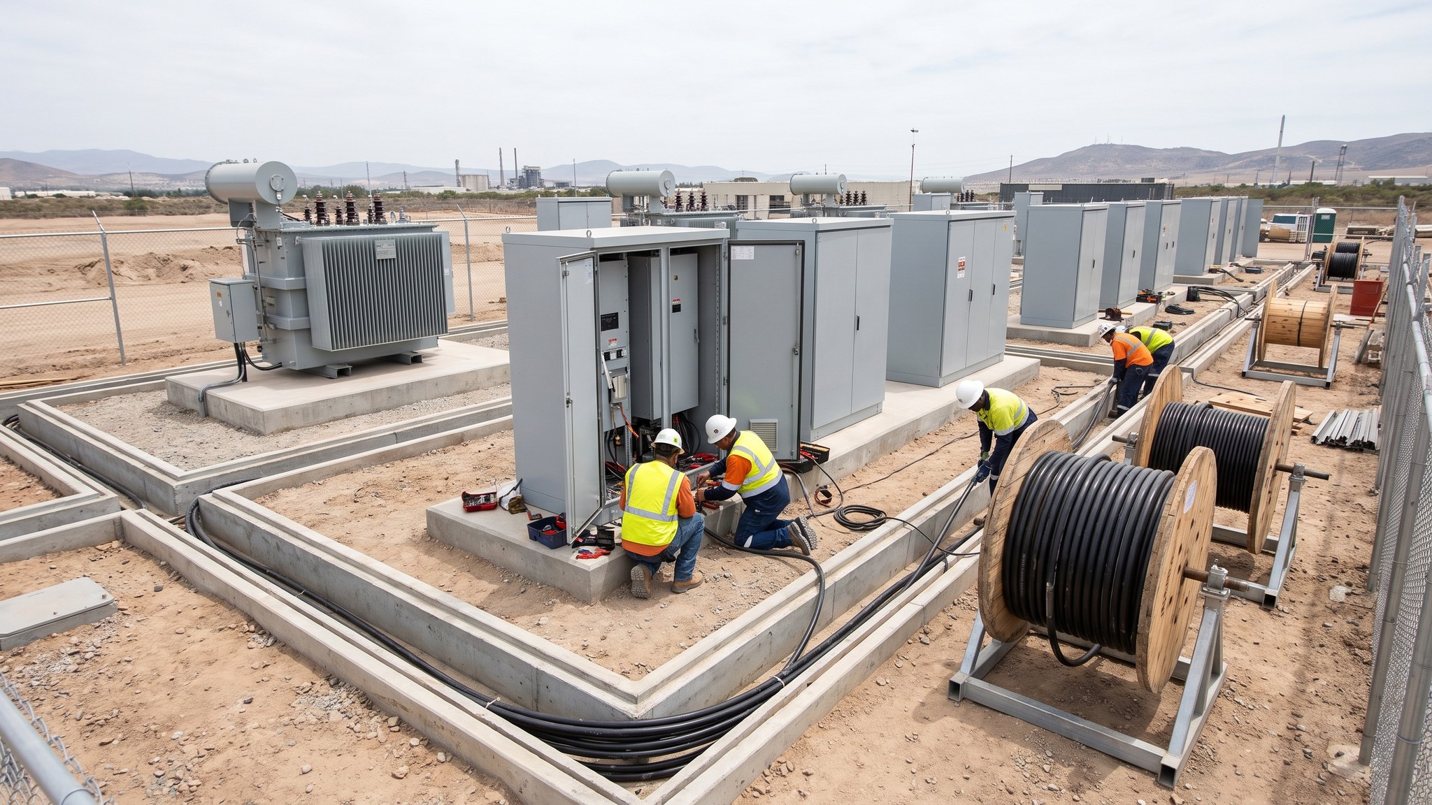
What is Integrated power blocks?
An integrated power block is a battery storage unit that arrives with its power conversion equipment and its transformer already built into the same enclosure. The supplier assembles it, wires it, tests it and ships it as one item. On site the unit is craned onto its foundation, connected to the medium voltage cabling, connected to the control and communications network, and that is broadly the extent of the electrical work at that position. Everything inside the enclosure was completed and proved in a factory, under cover, by people who build the same thing every week. The project buys a finished product rather than a set of parts to be assembled in a field in February.
The attraction is the interface count. On a battery storage project, most of the risk that shows up during commissioning sits at the joints between one party's equipment and another's - the cable termination, the protection settings, the control signal that was meant to arrive and did not. An integrated block removes a whole layer of those joints because the battery, the conversion equipment and the transformer were never separate parties to begin with. It also removes a whole layer of argument about who owns a fault. If the block does not perform, the supplier owns it. On most projects that single line in the contract is worth more than the equipment price difference, and it is why integrated blocks have become the default on repeatable schemes where the site is not unusual.
What the project gives up is flexibility. The block is what the supplier makes. Its footprint, its arrangement, its access requirements, its ventilation openings and its fire strategy assumptions are fixed by the manufacturer, and the site layout is drawn around them rather than the other way round. Replacing conversion equipment later means going back to the same supplier, or replacing the whole unit. Maintenance is carried out inside a sealed product on the supplier's terms, which is efficient while the relationship is good and awkward when it is not. The fire engineer also inherits the manufacturer's enclosure rather than designing one, and has to work with the separation, detection and ventilation arrangements that come with it. On most projects the decision is settled early, at concept stage, because the entire layout, the civils and the cabling design follow from it.
How does Integrated power blocks work, step by step?
- 1
Step 1: Settle the arrangement at concept stage
The choice between integrated blocks and separate conversion plant is made before the layout is drawn, because everything else follows from it. The electrical designer sets out what the connection point requires, the developer sets out the capacity and the duration the project is being built to trade, and the fire engineer confirms what each candidate arrangement would demand in space and separation. Comparing arrangements on unit price alone is the classic mistake. The comparison that matters covers land take, civils, cabling, spares, maintenance access and who carries the performance risk, over the whole life of the project rather than the construction period.
- 2
Step 2: Fix the block specification with the supplier
Once the arrangement is chosen the supplier's standard product is reviewed against the project. Enclosure size and weight drive the foundations and the crane. Ventilation and access openings drive the spacing and the orientation. The control interface drives what the wider site control system has to speak. The specification records what the block must do, and the supplier confirms what its product does, and any gap between those two is closed on paper long before delivery. Late changes to a factory-built product are expensive and are often simply refused.
- 3
Step 3: Build the foundations and the routes to suit the product
Foundations are designed for the block's point loads, its fixings and its tolerance for differential movement, which for a unit containing its own transformer is usually tighter than people assume. Cable routes, ducts and pits are set out to arrive where the block's entries are, not where the civils contractor would prefer. Access roads and hardstandings are designed for the delivery vehicle and the crane, and for the same vehicle returning years later to take a unit away. Getting a unit out again is a design case, not an afterthought.
- 4
Step 4: Take delivery and verify what arrived
Blocks are tested at the factory before despatch, and the project should witness or at least receive the results of that testing rather than discovering problems on site. On arrival each unit is checked for transport damage, for the correct configuration, and for the documentation set that the commissioning team will later need. Units are heavy, awkward and delivered on a tight sequence, so the lift plan, the ground conditions under the crane and the delivery order are all agreed in advance. A unit set down in the wrong position is a bad day.
- 5
Step 5: Place, fix and connect
Each block is lifted onto its foundation, levelled, fixed down and earthed in accordance with the electrical designer's drawings. The medium voltage cabling is brought in and terminated by the competent parties named for that work, and the control and communications cabling is landed and labelled. Terminations and labelling are the two items that consistently cost time later, so they are inspected as they are completed rather than at the end. Nothing is energised at this stage and the site remains a construction site.
- 6
Step 6: Integrate the blocks into one plant
Individually the blocks are products. Collectively they have to behave as a single power station, which means the site controller has to see every block, dispatch every block and receive back what it needs from every block. That integration is done by the control system supplier working with the block supplier, and it is where most of the schedule risk on an integrated scheme actually sits. Interface testing is planned as a task in its own right, with its own duration, rather than assumed to happen during commissioning.
- 7
Step 7: Hand the block interface into commissioning
Before the commissioning sequence starts, the responsibility for each block passes formally from installation to the commissioning team, with a documented record of what has been installed, inspected and left unenergised. The block supplier is present for the steps that concern its equipment, because the warranty on a factory-built product usually depends on it. From this point the site moves onto the commissioning process, which is a sequence of formal authorisations rather than a single handover.
- 8
Step 8: Plan for replacement from the beginning
A battery unit is a consumable on a long timescale. Cells degrade, conversion equipment is superseded, and augmentation or replacement is expected within the operating life of most projects. The layout, the access roads, the crane standings and the spares strategy are all set up on day one for a unit to be taken out and another put in, with the supplier's route back to site understood. Projects that treat the blocks as permanent fixtures pay for it later.
What are the benefits of Integrated power blocks?
- Fewest site interfaces of any arrangement, which removes a whole class of commissioning problems
- Performance and fault responsibility sits clearly with one supplier
- Factory assembly and factory testing in controlled conditions rather than site conditions
- Compact footprint, so less land is taken by conversion plant and cabling
- Fast to install once foundations and routes are ready, with a short and repeatable connection scope at each position
- Well suited to repeatable schemes where the same product is deployed across several sites
What are the limitations of Integrated power blocks?
- The layout is drawn around the manufacturer's product rather than the site
- Very little scope to change the arrangement once the product is selected
- Replacement and augmentation usually mean returning to the same supplier
- The fire engineer inherits the manufacturer's enclosure arrangements rather than designing them
- Maintenance access is on the supplier's terms and inside the supplier's product
- Heavy single units make delivery, craneage and future removal a design case in their own right
What is Integrated power blocks best suited for?
What plant does Integrated power blocks need?
- Mobile cranes sized for the heaviest single unit, with prepared standings
- Low loaders and escort arrangements for oversized deliveries
- Excavators, dozers and rollers for foundations, hardstandings and access roads
- Cable drum trailers, winches and rollers for the medium voltage cabling
- Jointing and termination equipment operated by the competent parties named for that work
- Test and diagnostic equipment brought in by the commissioning team
How is Integrated power blocks quality-checked?
- Factory test records received and reviewed before despatch, not after delivery
- Delivery inspection for transport damage and correct configuration on every unit
- Foundation levels, fixings and earthing verified against the electrical designer's drawings
- Cable terminations and labelling inspected as completed rather than at the end of the works
- Control and communications interfaces proved block by block against the control system specification
- A documented, unenergised handover into the commissioning process for every position
More power conversion & hv connection methods
Next method
Separate conversion plant and transformers