Separate conversion plant and transformers
Standalone conversion equipment and transformers serving many battery units - easier to maintain and replace, at the cost of more cabling and more civils.
Last updated 2026-09-06
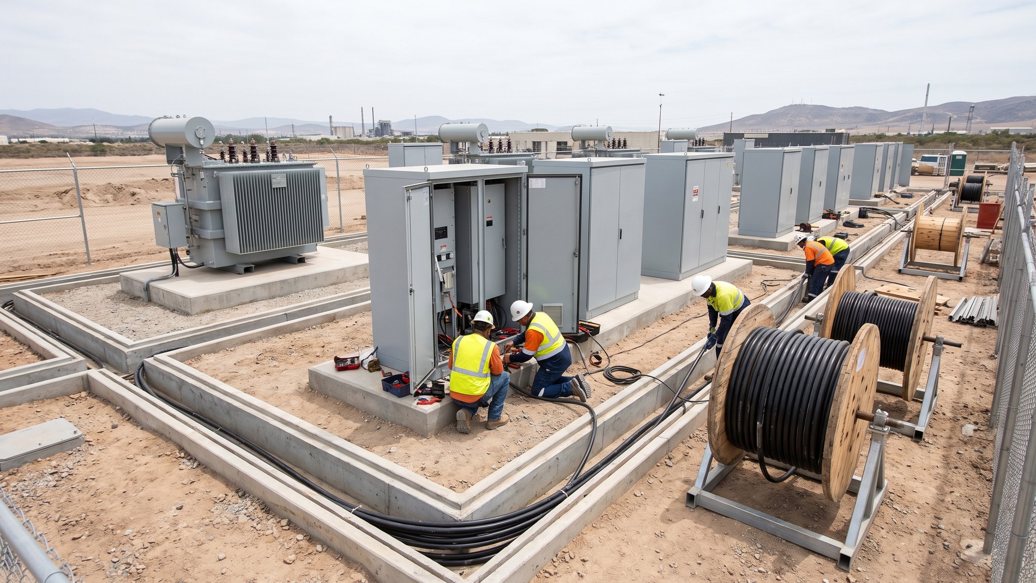
What is Separate conversion plant and transformers?
In this arrangement the batteries are one thing and the equipment that converts and transforms their output is another. Rows of battery enclosures are cabled back to conversion plant and transformers standing in their own positions, each set serving a number of battery units. It is the traditional power station arrangement applied to storage, and it is what most large projects and most projects with any complication end up building. The conversion equipment is sized, located and maintained as plant in its own right rather than as part of a product.
The advantage is that everything is reachable and everything is replaceable. Conversion equipment has a shorter useful life than the civils and often a shorter life than the batteries, and technology in this area moves quickly. When conversion plant is a separate item it can be maintained without opening a battery enclosure, replaced without replacing batteries, and upgraded when better equipment exists. Batteries can be added or replaced without touching the conversion plant. Faults are easier to isolate because the equipment is accessible and instrumented as a discrete item. For an owner planning to operate an asset for decades, that separation is worth a great deal, and it is why operators with large portfolios frequently prefer it even where an integrated product would be cheaper to build.
The cost is on site. Separating the equipment means low voltage cabling from every battery position to the conversion plant, more cable routes, more ducts, more pits, more terminations and more foundations. Each of those is a place where something can be wrong, and cabling losses and voltage drop become a design consideration that an integrated block simply does not have. The layout has to find room for conversion plant and transformers as well as batteries, and the fire engineer has to consider them as items on the site in their own right, with their own separation requirements set by that assessment. It takes longer to build, it costs more in civils, and it is the right answer whenever the site is unusual, the scheme is large, or the owner intends to operate rather than sell.
How does Separate conversion plant and transformers work, step by step?
- 1
Step 1: Size and locate the conversion plant
The electrical designer establishes how many battery units each set of conversion plant will serve and where those sets sit on the site. The arrangement balances cable lengths against the number of conversion positions: fewer, larger positions mean less equipment and more cabling, more positions mean the reverse. Losses, voltage drop, maintenance access, fire separation and the practicalities of getting a transformer in and out all feed the answer. This is settled at design stage because it drives the entire civils package.
- 2
Step 2: Design the cable routes as a system
The cabling between the battery positions and the conversion plant is not incidental - on a separated scheme it is one of the largest single packages on the project. Routes, duct capacity, pit positions, bending radii, segregation between power and control, and future spare capacity are all designed before anything is dug. Getting duct routes wrong is one of the more expensive mistakes available on a battery project, because the correction is buried under finished hardstanding.
- 3
Step 3: Build the foundations, plinths and containment
Conversion plant and transformers need designed foundations, and transformers usually need bunding or containment for their fluids where the specification calls for it. Plinths, access hardstandings, ducts and pits are constructed together so that the routes and the equipment positions arrive at the same coordinates. Setting out is checked against the equipment supplier's certified drawings rather than the tender drawings, because equipment dimensions move between tender and manufacture more often than anyone expects.
- 4
Step 4: Place and fix the equipment
Conversion units and transformers are delivered and set on their foundations, levelled, fixed and earthed to the electrical designer's drawings. Transformers in particular are heavy, sensitive to how they are handled and slow to replace, so delivery, lifting and setting are planned in detail. Equipment is protected and kept dry from the moment it lands, because plant standing open on a construction site accumulates problems that only appear at commissioning.
- 5
Step 5: Install and terminate the cabling
Cables are pulled, laid, identified and terminated by the competent parties named for that work. Every core is labelled at both ends and recorded. This is repetitive work carried out over a long period by a large team, which is exactly the condition in which quality drifts, so terminations are inspected progressively and the records are kept current rather than assembled at the end. The cable schedule at handover has to match what is actually in the ground.
- 6
Step 6: Install protection and control
Separated schemes need protection and control equipment that sees the battery positions, the conversion plant and the connection to the network as one system. Panels are installed, wired and labelled, and the settings that will later be applied are prepared by the electrical designer. Nothing is applied or proved at this stage. The installation work simply puts the equipment in place ready for the commissioning process to prove it in the correct sequence.
- 7
Step 7: Prove the installation before it goes anywhere near live
The whole separated installation is checked while it is unenergised: continuity and identification of every cable, correct terminations, correct earthing, correct labelling, and agreement between the installed arrangement and the drawings. Discrepancies are corrected and the drawings updated. This is unglamorous work and it is the single biggest determinant of how long commissioning takes on a separated scheme.
- 8
Step 8: Set the asset up to be maintained
The point of separating the plant is that it can be looked after, so the project finishes by making that real. Access routes are clear, maintenance space is not built over, spares are identified, equipment is labelled consistently with the operating documentation, and the asset register matches what is on the ground. An operator arriving in five years should be able to find, isolate and work on any item using the documents handed over.
What are the benefits of Separate conversion plant and transformers?
- Conversion equipment can be maintained, replaced or upgraded without touching the batteries
- Batteries can be replaced or augmented without replacing the conversion plant
- Faults are easier to isolate and diagnose on accessible, discrete equipment
- The layout can be shaped to the site rather than to a manufacturer's product
- Suits large schemes where a single packaged product does not scale sensibly
- Attractive to long-term owners and operators rather than developers building to sell
What are the limitations of Separate conversion plant and transformers?
- Substantially more cabling, ducts, pits, terminations and civils
- More interfaces, and therefore more places for commissioning problems to appear
- Cabling losses and voltage drop become a real design consideration
- Larger land take, because conversion plant and transformers need their own positions
- Longer construction programme than a packaged arrangement
- More parties involved, so coordination and interface management take real effort
What is Separate conversion plant and transformers best suited for?
What plant does Separate conversion plant and transformers need?
- Mobile cranes for conversion units and transformers, with prepared standings
- Low loaders and specialist transport for transformer deliveries
- Excavators, trenchers and rollers for duct routes, pits and hardstandings
- Concrete plant for plinths, bunds and containment structures
- Cable drum trailers, winches, rollers and pulling gear
- Jointing and termination equipment operated by the competent parties named for that work
How is Separate conversion plant and transformers quality-checked?
- Setting out checked against certified equipment drawings, not tender drawings
- Duct routes, pits and spare capacity recorded as built before they are covered
- Every cable core identified, labelled at both ends and recorded on the cable schedule
- Terminations inspected progressively through the works rather than at completion
- Earthing verified across the whole installation against the electrical designer's drawings
- Full unenergised verification of the installation before the commissioning process begins