Individual plinths or ground beams
Discrete bases under each unit - far less concrete, far less tolerance for a setting-out error.
Last updated 2026-09-06
What is Individual plinths or ground beams?
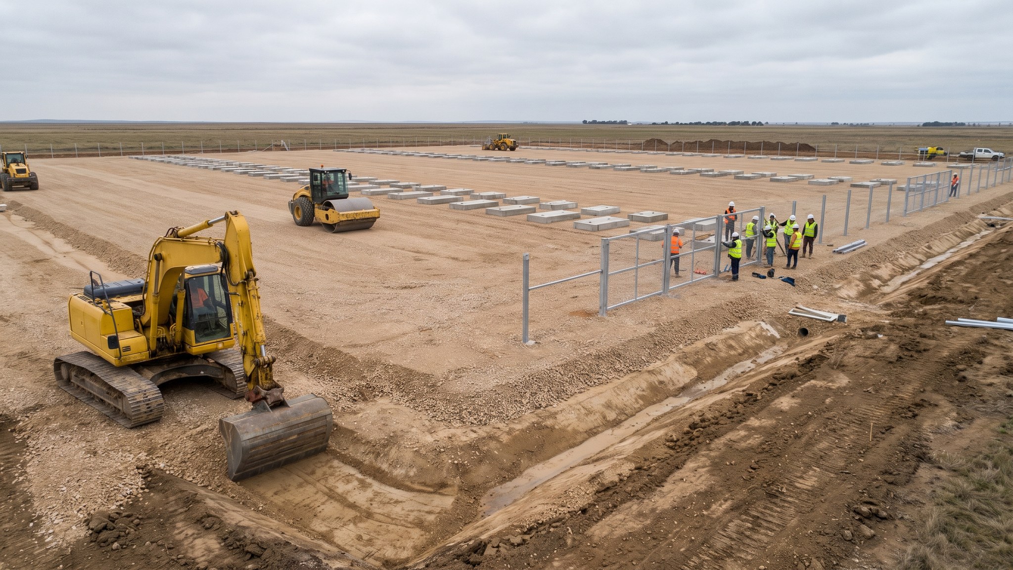
Individual plinths or ground beams put concrete only where the load is. Instead of one continuous raft, each unit sits on its own pair of beams, its own pad group or a short run of beam shared between neighbouring units, and the ground between is left to be surfaced separately. On most projects this cuts the concrete quantity substantially against a raft, and it cuts the programme with it, because the pours are small, repetitive and far less weather-critical. It is a common choice on battery storage sites where the units are supported at defined bearing points rather than across their whole footprint, which is how many factory-built enclosures are designed to sit.
What the option gives back in quantity, it takes in precision. A raft forgives; a plinth does not. The bearing points on the unit have to land on the bearing points of the base, in plan and in level, and the tolerance is set by the battery supplier rather than by the civils contractor. That means the setting out has to be surveyed, checked and recorded before the pour, and the finished levels have to be surveyed after it. Where several units share a run of beam, a small cumulative error along the run becomes a large error at the end of it. Experienced teams set out from a single control network across the whole compound rather than from unit to unit, and they check the last base against the first before anything is poured.
The second consequence is that the ground between the bases still has to be dealt with. It needs a surface that can carry a delivery vehicle and a crane, it needs to drain, and it needs to be maintainable for the life of the site. That is usually a granular surface, sometimes a bound one on the access routes, and it comes with its own drainage design. So the saving against a raft is real but smaller than the concrete quantity alone suggests. The designer decides the base arrangement, its dimensions and its reinforcement from the ground investigation and the loads the battery supplier gives, and the fire strategy and layout set by the design team fix where the bases go. As with any option, craneage and delivery access govern the arrangement, because every unit has to be reachable, and discrete bases at end of life are easier to break out and remove than a continuous raft - a genuine advantage where the consent is time-limited.
How does Individual plinths or ground beams work, step by step?
- 1
Step 1: Take the bearing arrangement from the battery supplier
The starting point is the supplier information for the unit: where it bears, how much load arrives at each bearing point, what tolerance is allowed in plan and in level, and how the unit is fixed down. Plinths and beams are designed to that information and nothing else. Where the supplier is not appointed when the civils design starts, the design is either held or carried at risk, and carrying it at risk on this option is expensive.
- 2
Step 2: Establish a single control network across the compound
One survey control network is set up for the whole array and every base is set out from it. Setting out unit to unit accumulates error along a row and leaves the last base out of position. The control network is also what the installation team will use later, so it is protected and left in place.
- 3
Step 3: Investigate the ground and design the bases
The ground investigation determines what each base bears on, the formation level and the settlement expected. Because the load is concentrated rather than spread, the bearing conditions under each base matter more than they would under a raft, and variable ground across a compound can mean the designer sets different arrangements in different areas. Where the ground will not carry a shallow base, the design moves to piles or screw piles.
- 4
Step 4: Excavate and prepare each base
Bases are excavated to the designed formation, the formation is inspected and accepted, and blinding is placed. This is a repetitive operation across many positions, and consistency is the thing to manage - a formation accepted on one base and assumed on the next is how a soft spot gets built over.
- 5
Step 5: Fix reinforcement and set the holding-down items
Reinforcement, any starter bars and the holding-down bolts, frames or sockets are set to the supplier drawings and checked independently. Templates are normally used so that every base in a row is set out identically. This is the highest-risk step in the whole option, because a fixing group in the wrong place is not discovered until a unit is hanging over it.
- 6
Step 6: Pour and cure the bases
The pours are small and can be sequenced around weather and around other activities, which is one of the real advantages of this option. Finished levels are surveyed as the concrete is placed and again once cured, and the survey is recorded against each base. Any base outside the supplier tolerance is corrected before the units arrive.
- 7
Step 7: Surface and drain the ground between the bases
The area between and around the bases is brought up to the designed surface - commonly a compacted granular finish, with bound surfacing on the access and crane routes - and the surface water drainage is completed. The surface has to carry a delivery vehicle and a crane to every position, so it is designed for the installation loads rather than for the operational ones.
- 8
Step 8: Survey, record and release for installation
A full as-built survey of every base and every fixing group is issued to the installation team and checked against the supplier tolerances before the first delivery. The bases are then protected, because a fixing group damaged by site traffic between the pour and the lift is a base that has to be repaired at the worst possible moment.
What are the benefits of Individual plinths or ground beams?
- Uses far less concrete and reinforcement than a continuous raft, with lower cost and embodied carbon
- Small repetitive pours are far less weather-critical and easier to fit around other activities
- Discrete elements are simpler to break out and remove at end of life, which suits a time-limited consent
- Puts foundation capacity only where the load actually arrives
- Allows different base arrangements in different ground conditions across the same compound
- A layout change affects a small number of bases rather than one large structure
What are the limitations of Individual plinths or ground beams?
- Demands accurate setting out, and the tolerance belongs to the battery supplier rather than the contractor
- Cumulative error along a shared beam run puts the last unit out of position
- Leaves the ground between the bases to be surfaced and drained as a separate work item
- Concentrated loads make variable bearing conditions more significant than under a raft
- Depends on the supplier information being available early, which it often is not
- Fixing groups are exposed to site traffic damage between the pour and the lift
What is Individual plinths or ground beams best suited for?
What plant does Individual plinths or ground beams need?
- Excavators for base excavation, with attachments for trimming and formation preparation
- Small concrete deliveries, skips or a pump for repetitive pours
- Steel fixing resources and reusable formwork or base templates
- Survey equipment and a protected control network across the compound
- Rollers and compaction plant for the granular surface between the bases
- Mobile crane and delivery vehicle access to every base position
How is Individual plinths or ground beams quality-checked?
- Battery supplier bearing loads, fixing arrangement and tolerances obtained and issued before design
- Single survey control network established, protected and used for every base
- Each base formation inspected and accepted individually rather than by assumption
- Fixing groups set from templates and independently checked in plan and level before the pour
- As-built survey of every base and fixing group issued to the installation team and signed off against the supplier tolerance
- Bases protected from site traffic between the pour and the lift, with damage reported and repaired before delivery