Reinforced concrete slab or raft platform
One continuous slab under the whole array - the simplest thing to set out and the heaviest thing to build.
Last updated 2026-09-06
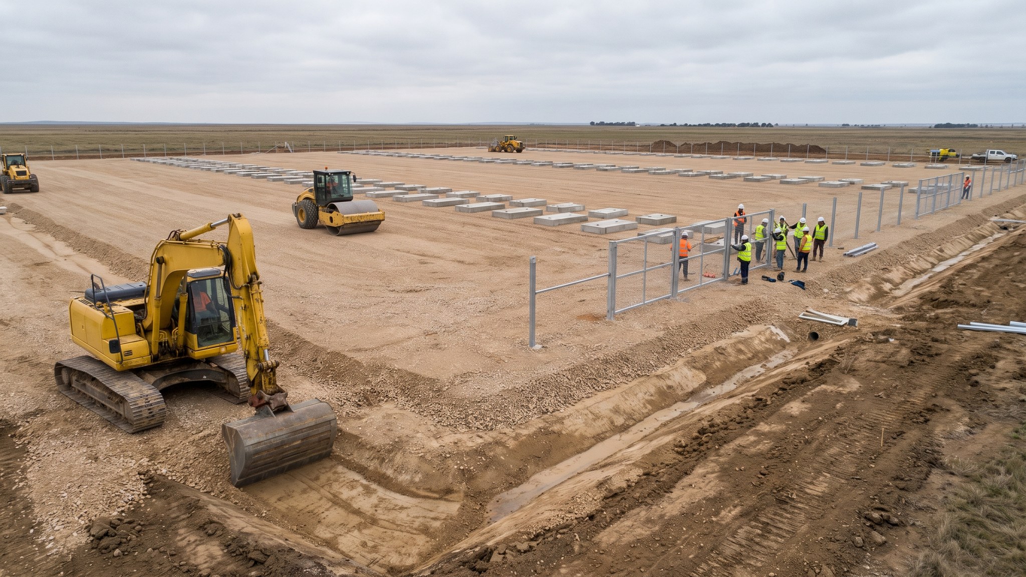
What is Reinforced concrete slab or raft platform?
A reinforced concrete slab or raft platform is a single continuous structure cast across the footprint of the battery array, with the units, the conversion equipment and often the access routes all sitting on the same piece of concrete. It is the most straightforward answer to a battery storage site because it removes almost every setting-out problem in one move. The units do not have to find individual bases. They are positioned on a flat, level, load-bearing surface, and small differences between one delivery and the next are absorbed by the slab rather than argued over on site. Where a project has many identical units in tight rows, and where the client wants a hard, clean, drained surface for the life of the consent, this is commonly the option the designer reaches for first.
The trade-off is quantity. A raft uses far more concrete, far more reinforcement and far more programme than any of the alternatives, and on most projects it is the single largest civils item on the site. It also concentrates the work into a small number of large, weather-dependent operations - excavate, form up, fix reinforcement, pour, cure - each of which has to land in sequence. Because the battery units arrive to a fixed delivery date agreed with the supplier long in advance, the slab sits squarely on the critical path. A pour lost to weather is not recovered by working weekends at the end. It is recovered by finding somewhere to stand a container that has already left the factory. The designer decides the slab arrangement, its thickness and its reinforcement from the ground investigation, the loads given by the battery supplier and the settlement the equipment will tolerate, and none of those figures can be assumed from another project.
Two design inputs shape a raft on a battery project more than they would on an ordinary industrial slab. The first is craneage. Every unit is lifted from a delivery vehicle onto its final position, so the slab has to carry not only the units but the crane and the outriggers that place them, and the access route has to let a vehicle and a crane reach every position in a sequence that does not strand the last unit behind the first. The second is end of life. Many battery storage consents are time-limited, and the site is expected to be cleared and the land returned at the end of the term. A raft is durable and easy to live with, but it is also the hardest of the options to take out, and the decommissioning cost belongs in the appraisal at the start rather than at the end. Lithium battery systems carry a thermal runaway hazard, and that hazard is one of the reasons the layout, the spacing of the units and the overall fire strategy are engineered by the design team rather than arranged on site - the slab simply has to suit the layout they set.
How does Reinforced concrete slab or raft platform work, step by step?
- 1
Step 1: Fix the layout before the civils design starts
Nothing about the slab can be settled until the equipment layout is settled. The battery supplier gives the footprint, the weight and the bearing arrangement of each unit, the designer sets the positions, the orientations and the routes between them, and the fire strategy and the electrical arrangement both push back on that layout. Only then does the civils design have a shape to work to. On most projects this is the step that runs late, and a slab designed against a layout that later moves is a slab that gets broken out.
- 2
Step 2: Investigate the ground and set the formation
The ground investigation establishes what is under the site, where the water sits and how much the ground will settle under the loads the supplier has given. The designer uses that to decide the formation level, whether any material has to come out, and whether the ground is capable of carrying a raft at all. Where it is not, the answer is usually a piled or screw-pile solution rather than a thicker slab. Made ground, old foundations and buried obstructions are common on the brownfield sites these projects favour, and they are cheaper to find now than during the dig.
- 3
Step 3: Strip, dig and prepare the sub-base
Topsoil and unsuitable material are stripped and stockpiled or removed, the formation is trimmed to level and proof-rolled, and the granular sub-base is placed and compacted in layers. This is the part of the project where the earthworks quantities are proved right or wrong, and where the surface water arrangements start to bite, because an open formation in a wet week is a formation that has to be redone. The designer sets the sub-base and any capping from the ground investigation.
- 4
Step 4: Install everything that has to pass under the slab
Cable ducts, earthing, drainage and any containment or below-ground services are placed, surveyed and recorded before the slab goes over them. Once the concrete is down, anything missed is a saw cut and a delay. The as-built survey of these below-slab items matters more on a battery project than on most, because the cable routes between the units and the conversion equipment are dense and the tolerances at the connection points are tight.
- 5
Step 5: Form up, fix reinforcement and set the cast-in items
Edge formwork, movement joint arrangements, reinforcement and any cast-in fixings, frames or holding-down items are set out and checked against the equipment layout. The cast-in items are the single highest-risk element - they are set to the battery supplier drawings, and a fixing in the wrong place is discovered on the day the crane arrives. Independent checking of positions and levels before the pour is time very well spent.
- 6
Step 6: Pour, finish and cure the slab
The slab is poured in the bays and sequence the designer has set, finished to the specified surface tolerance and cured. Surface regularity matters because the units are set down on it and levelled off it, and a slab that is out of tolerance turns into shimming and packing on the day of installation. Pours are weather-dependent, and on a project with a fixed delivery date the programme normally carries some allowance for lost days.
- 7
Step 7: Complete the surrounding works and drainage
Access roads, hardstandings, crane standings, perimeter works and the surface water drainage are completed around the slab, along with any bunding, attenuation or interception the designer has specified. The site has to be able to take a delivery vehicle and a crane at every unit position in all weathers, because deliveries do not wait for a dry week.
- 8
Step 8: Survey, record and hand over to installation
The finished levels, the cast-in positions and the below-slab services are surveyed and recorded, and the platform is formally handed to the installation team against the tolerances the battery supplier requires. Any items outside tolerance are corrected before the first unit arrives. From this point the slab is a working surface, and protection from site traffic, spillage and stored materials becomes a daily concern.
What are the benefits of Reinforced concrete slab or raft platform?
- Simplest option to set out, because the units find a level surface rather than individual bases
- Absorbs small differences between units and between deliveries without rework
- Gives a hard, clean, drained surface across the whole array for the life of the site
- Spreads load over a large area, which suits sites with variable but adequate ground
- Provides a ready-made crane standing and access surface for both installation and later replacement
- Durable and low maintenance once complete, with few discrete elements to inspect
What are the limitations of Reinforced concrete slab or raft platform?
- Uses the most concrete and reinforcement of any of the platform options, with the embodied carbon that implies
- Longest and most weather-dependent programme, on a project where the delivery date is fixed
- Hardest option to remove at end of life, which matters where the consent is time-limited
- Cast-in items have to be exactly right, because errors are only found when the crane arrives
- Concentrates risk into a small number of large operations rather than spreading it
- Ties the whole array to one structure, so a layout change late in the design is expensive
What is Reinforced concrete slab or raft platform best suited for?
What plant does Reinforced concrete slab or raft platform need?
- Excavators and dozers for strip, dig and formation trimming
- Dumpers and rollers for sub-base placement and compaction
- Concrete supply, pumps or chutes, and power float or laser screed finishing equipment
- Steel fixing and formwork resources, with lifting for reinforcement deliveries
- Survey equipment for formation, cast-in items and finished levels
- Mobile crane and delivery vehicle access for the installation phase that follows
How is Reinforced concrete slab or raft platform quality-checked?
- Equipment layout and battery supplier loads frozen and issued before the civils design is completed
- Formation proof-rolled and accepted, with compaction testing on the sub-base against the specification
- Below-slab ducts, earthing and drainage surveyed and recorded as-built before the pour
- Cast-in fixings and frames independently checked for position and level against the supplier drawings
- Concrete testing and curing records kept, with surface regularity measured against the specified tolerance
- Final level survey handed to the installation team, with any out-of-tolerance areas corrected before delivery
More site preparation & civils methods
Next method
Individual plinths or ground beams