Compression plus liquid pumping
Compress part of the way, then pump as a dense liquid - usually the more efficient route to an export condition.
Last updated 2026-09-06
What is Compression plus liquid pumping?
Compressing a gas all the way to an export condition is expensive in energy, because the work rises steeply as the gas is squeezed. Carbon dioxide has a useful property: once it has been raised far enough it can be condensed to a dense liquid, and a liquid is far cheaper to move onwards. A pump does the same job as the remaining compression stages for a small fraction of the power. So a very common arrangement on export projects is a hybrid - a compressor train that takes the stream part of the way, a cooling step that condenses it, and a pump that takes the dense liquid the rest of the way to what the pipeline or the shipping terminal requires.
The attraction is straightforward. Pumping a liquid consumes markedly less energy than compressing a gas over the equivalent range, and on a capture project the parasitic energy load is one of the main things the whole scheme is judged on. Fewer compression stages also means a shorter, cheaper machine and less interstage cooling. The design work sits in the middle of the chain, at the point where the stream changes from a gas being compressed to a liquid being pumped. The stream has to arrive at the pump as a stable liquid, reliably and through every operating condition the plant will see, and the pump has to be protected from ever seeing anything else. Where that transition sits, how it is cooled and how it is controlled is the designer's decision and it is the heart of the scheme.
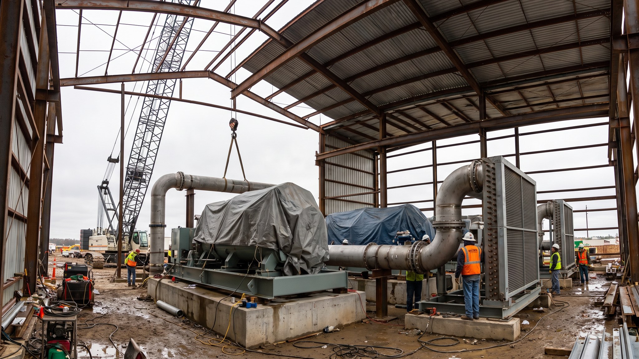
For the construction team a hybrid arrangement means two quite different packages that have to work as one. The compressor package is heavy rotating plant on a substantial foundation. The pump package is smaller, but it is a machine handling a dense liquid with its own materials, sealing and protection requirements, and it usually needs a cooling or refrigeration system alongside it to hold the condition at inlet. The two are tied together by control rather than by pipework alone, and the commissioning sequence has to prove the transition works before it proves the throughput. On projects that also load ships, the same condensing philosophy carries through, because a ship is loaded with a liquid cargo in any case - which is why hybrid arrangements and marine export tend to appear together.
How does Compression plus liquid pumping work, step by step?
- 1
Step 1: Decide the split between compression and pumping
The designer establishes where the stream should stop being compressed and start being pumped. The decision balances the power saved by pumping against the cost and complexity of the cooling or refrigeration needed to condense the stream reliably, and against how stable the plant will be through turndown and upsets. This is the defining decision of the whole scheme and everything downstream follows from it. On most projects several splits are evaluated before one is fixed.
- 2
Step 2: Size the compression stages to the transition point
With the split fixed, the compressor train is configured to reach it - typically fewer stages than a full compression scheme, with intercooling and interstage separation as any compression duty requires. Because the machine is smaller, more options open up on machine type and on the electrical connection, and on some projects that in turn changes the substation design. The duty is still set from both ends, but the downstream end is now the pump inlet condition rather than the export condition.
- 3
Step 3: Design the cooling or refrigeration that produces a stable liquid
Condensing the stream reliably needs cooling, and depending on the site and the ambient conditions that may be cooling water, air cooling, a refrigeration package, or a combination. The design has to work on the hottest day as well as the coldest, because the transition must not become marginal seasonally. On a site with limited cooling water the refrigeration package can become a significant plot, power and noise item in its own right. The utility demand this creates is confirmed early, because it competes with the capture plant for the same site resources.
- 4
Step 4: Select the pump and the materials for dense liquid duty
The pump is selected for the fluid it will actually handle, not for a generic liquid duty. Materials, sealing arrangement, bearing selection and the protection against running dry or running back are all specified by the designer with the pump supplier. Dense liquid carbon dioxide is a demanding fluid for seals, and the sealing arrangement is a specified item rather than a supplier standard. Spare capacity is usual, because a pump failure stops export just as completely as a compressor failure.
- 5
Step 5: Install the two packages and the transition between them
Civil and mechanical installation follows the pattern for each package - a substantial foundation and precision setting for the compressor, a smaller but still carefully aligned installation for the pump, and the cooling or refrigeration plant with its own structures and services. The pipework between them is short but critical: it carries the stream through its change of state and it is where instrumentation is concentrated. Insulation and cold service detailing appear here and are specified accordingly.
- 6
Step 6: Engineer the control across the transition
The plant is controlled as one system, not as a compressor with a pump bolted on. The control has to hold the condition at pump inlet through load changes, through start-up and shutdown, and through upsets on the capture plant, and it has to protect the pump automatically if that condition is lost. The interlocks between the compressor, the cooling system, the pump and the export route are engineered together and tested together. This is the part of a hybrid scheme that takes the most commissioning effort.
- 7
Step 7: Commission the transition before the throughput
Commissioning proves the chain in order: compression to the transition point, then stable condensing, then pumping, then the whole train at load. The point of the sequence is that the transition is proved stable before the plant is asked to run hard through it. Turndown behaviour is tested deliberately, because the transition is most fragile at low load and that is exactly where a capture plant following a variable host process will spend time.
- 8
Step 8: Hand over with the operating envelope written down
The operator inherits a plant with an operating envelope defined by where the transition stays stable. That envelope, the protections that enforce it, the seasonal limits from the cooling design and the actions required when the plant leaves it are documented and trained out at handover. A hybrid scheme is efficient precisely because it is operated inside its envelope, so the envelope is part of the deliverable.
What are the benefits of Compression plus liquid pumping?
- Markedly lower power than compressing the whole way, which improves the energy balance of the capture scheme
- Fewer compression stages, so a smaller and cheaper compressor package
- Less interstage cooling and separation duty on the compressor itself
- Fits naturally with marine export, where a liquid cargo is wanted in any case
- Pumps are smaller, cheaper and easier to spare than additional compression stages
- Lower electrical demand at the largest single load, which can simplify the site connection
What are the limitations of Compression plus liquid pumping?
- Adds a cooling or refrigeration system with its own plot, power, noise and maintenance burden
- The transition must be held stable through every operating condition, including turndown and upsets
- Seasonal ambient variation has to be designed for or the transition becomes marginal in summer
- Pump sealing and materials for this fluid need specific attention and are not a catalogue selection
- More complex control and interlocking than a straight compression train, and more commissioning effort
- Two packages and two suppliers to coordinate, with the interface between them carrying the risk
What is Compression plus liquid pumping best suited for?
What plant does Compression plus liquid pumping need?
- Compressor train sized to the transition point, with its intercooling and separation
- Cooling water system, air-cooled exchangers or a refrigeration package as the design requires
- Dense liquid pumps with their drivers, seals and protection systems, normally with spare capacity
- Insulated and cold-service pipework and instrumentation across the transition
- Integrated control system covering both packages and the interlocks between them
- Electrical supply, switchgear and control rooms for both packages
How is Compression plus liquid pumping quality-checked?
- Design case for the compression and pumping split documented, including the turndown and seasonal cases
- Cooling or refrigeration performance demonstrated across the design ambient range
- Pump materials, seal arrangement and protection certified for the specified service
- Cold service insulation and pipework details inspected before insulation is closed up
- Interlock and protection testing across the transition witnessed before operation on process
- Commissioning sequence proving stable condensing before load is applied, with results recorded
- Turndown behaviour tested and the stable operating envelope documented
- Operating envelope, protections and seasonal limits issued and trained out at handover