Integrally geared centrifugal compression train
The compact multi-stage machine that most large capture plants are built around - steady, continuous and unforgiving of a variable feed.
Last updated 2026-09-06
What is Integrally geared centrifugal compression train?
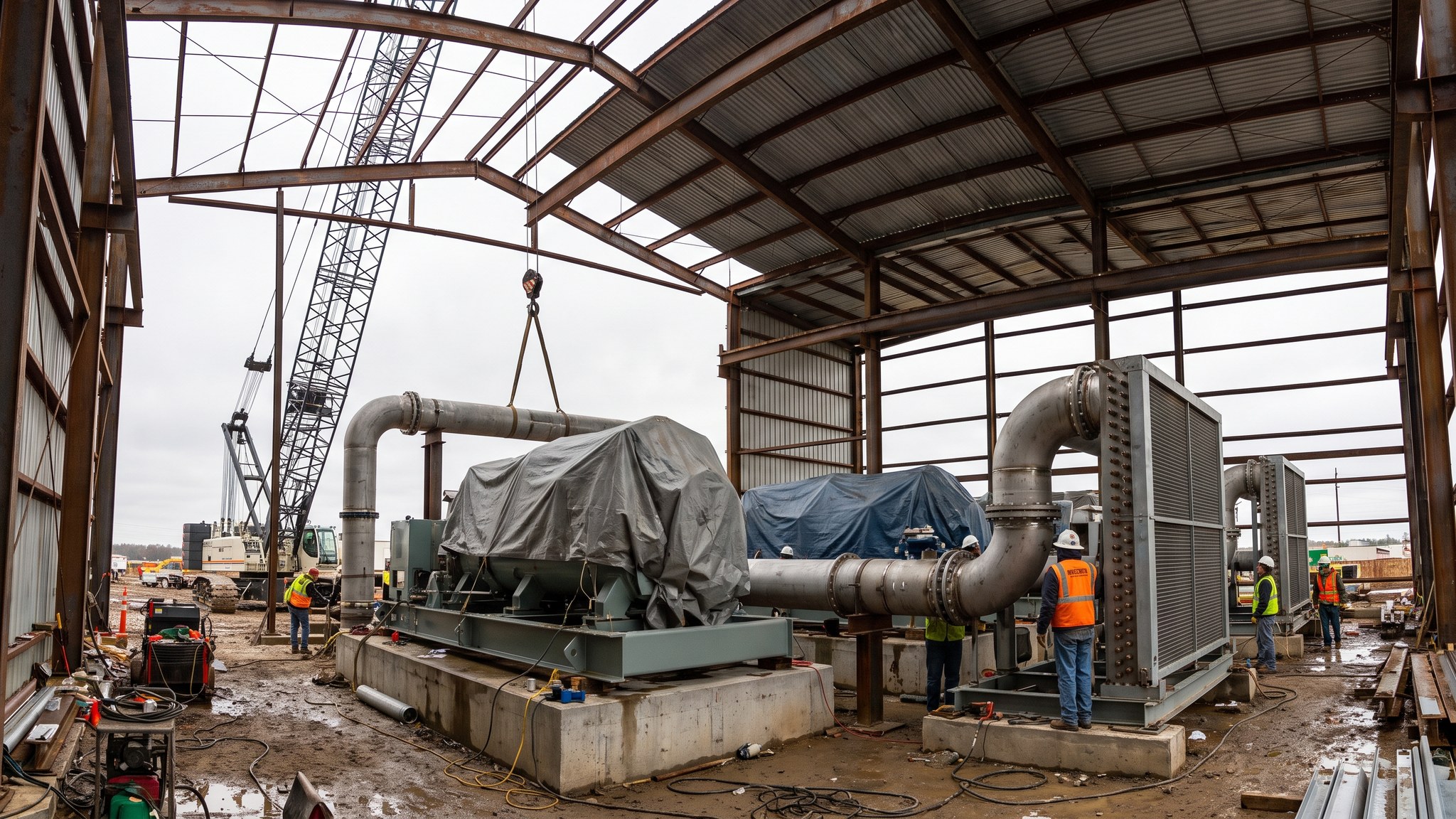
Captured carbon dioxide leaves a capture plant at close to atmospheric conditions and has to be raised to the state the pipeline or the ship demands. Compression is the machine that does it, and on most large projects the machine is an integrally geared centrifugal train. The arrangement is distinctive: a single large bull gear driven by one motor, with several small pinions arranged around it, each carrying one or two impellers. Because every stage can be geared to its own optimum speed, the train achieves a large overall rise in a short machine with a small footprint. Between stages the gas is cooled and the condensed water knocked out, which is why the skid looks less like a compressor and more like a compact process plant with a compressor inside it.
The reason this machine dominates the large end of the market is that carbon dioxide capture plants run continuously. A power station or an industrial cluster hub produces a broadly constant stream, and a centrifugal machine is at its best on constant duty. It has few reciprocating parts, long intervals between overhauls, no oil carryover into the process, and it can be laid out to a very compact plot - which matters enormously on a retrofit site where the capture plant has already taken the available space. The counterpart is that a centrifugal machine has a defined operating window. Push it too far down in throughput and the flow across an impeller becomes unstable, and the machine has to be protected against that condition by its own control system rather than by the operator noticing.
For the construction team the compression train is one of the heaviest and most schedule-critical items on the project. It arrives as a long-lead package, often on a single fabricated skid or on a small number of large modules, and it wants a substantial reinforced foundation, close-tolerance setting, a large cooling water or air-cooling connection, a dedicated electrical supply of a size that frequently drives the site substation design, and a great deal of interface engineering with both the capture plant upstream and the pipeline downstream. It also sits at a point where nothing is forgiving: the specification for what leaves the train is set by the pipeline designer and the storage operator, and the whole chain is held to it. The designer decides the number of stages, the intercooling arrangement and the machine selection, and those decisions are made long before the civil works start.
How does Integrally geared centrifugal compression train work, step by step?
- 1
Step 1: Fix the duty from the capture plant and the pipeline
The train is sized from two ends at once. Upstream, the capture plant sets the flow, the composition and how much that flow can swing across a day and across a year. Downstream, the pipeline designer and the storage operator set the condition the fluid must be delivered in and the purity it must meet. The gap between those two is the duty. On most projects the designer works through several machine configurations before settling, because the number of stages, the intercooling arrangement and the driver rating all move together. Turndown - how far the plant can drop in throughput and still run - is agreed at this stage rather than discovered later, because it decides whether recycle capacity is needed and how big it has to be.
- 2
Step 2: Select the machine and place the long-lead order
Compression trains are among the longest lead items on a capture project, commonly ordered well before the site is cleared. The order fixes the driver, the gear case, the number of pinions and impellers, the sealing arrangement and the materials in contact with the process fluid. Materials matter more here than on an ordinary air or gas machine, because the process stream can carry water and trace contaminants from the capture solvent. The designer and the machine supplier agree the material specification together. Once that order is placed the civil design is effectively frozen to it, so the project team treats the machine data as a gate rather than as information.
- 3
Step 3: Build the foundation and the plot around it
A geared train is a rotating machine on a common baseplate and it needs a foundation that will not move, will not settle differentially and will not amplify the machine's own running frequencies. That normally means a reinforced concrete block or table, designed by the structural engineer with the machine supplier's dynamic data in hand, on piles or on a competent stratum depending on the ground investigation. Around it the plot has to accommodate the intercoolers, the separators, the lube oil system, the control panel, the electrical room and - critically - the maintenance access to withdraw a pinion or a bundle. Access routes that look generous on a plan get consumed quickly once the pipework is modelled.
- 4
Step 4: Set, align and grout the train
The machine is landed, set on its shims or jacking screws, levelled and aligned to the tolerances the supplier states, and grouted. This is patient work carried out by a small specialist crew and it is not compressed to suit the programme. Alignment is checked cold, and on many projects checked again hot once the train has run, because a large geared machine and its driver move as they warm up. The supplier's representative is normally present and normally has to sign the alignment record before the coupling is made up.
- 5
Step 5: Install the intercooling and separation between stages
Compression heats the gas, and the heat has to come out between stages or the next stage cannot do its work. Cooling is by water or by air depending on what the site can supply, and on a coastal or estuarine site the cooling arrangement can be a consenting question in its own right. Cooling also condenses water out of the stream, so each stage discharges through a separator and the collected liquid is routed away. That water is not clean condensate - it is a process effluent and it is handled as one. Getting the interstage arrangement right is what makes the train efficient and what keeps liquid out of the next impeller.
- 6
Step 6: Tie the train into the control and protection system
A centrifugal machine cannot be left to find its own operating point. Its control system continuously compares where the machine is running against where it must not run, and it acts automatically to keep it clear. That protection, the vibration and temperature monitoring on every pinion, the driver protection and the interlocks to the capture plant and the pipeline are engineered as one system. The commissioning team proves the protection before it proves the performance - the order matters, because the first thing a new train does is find every weakness in the loop it sits in.
- 7
Step 7: Commission in stages against the specification
The train is commissioned progressively: mechanical completion, then the auxiliary systems, then a mechanical run, then operation on process. Each step is a documented hold point with the supplier, the operator and the commissioning engineer present. The final proof is not that the machine runs but that what leaves it meets the specification the pipeline designer wrote, continuously and through the turndown range agreed at the start. Performance testing is witnessed and the results form part of the handover documentation.
- 8
Step 8: Hand over with the maintenance regime defined
A geared train is a long-life asset with a defined overhaul cycle, and the operator inherits it with a maintenance strategy, a spares holding and a condition monitoring baseline. The baseline vibration and thermal signatures taken during commissioning are the reference that every later inspection is measured against, so they are recorded properly rather than treated as a formality. Access, lifting provision and laydown for a future overhaul are confirmed as built, because a machine that cannot be maintained in place becomes a shutdown problem for the whole chain.
What are the benefits of Integrally geared centrifugal compression train?
- Compact multi-stage arrangement in a small plot, which suits congested retrofit sites
- Well matched to the steady continuous duty that a large capture plant produces
- Each stage can run at its own optimum speed, giving good efficiency across the train
- Few reciprocating parts, long overhaul intervals and low maintenance labour compared with reciprocating machines
- No oil carryover into the process stream from the compression itself
- Single driver and single skid simplifies the electrical and structural interface
What are the limitations of Integrally geared centrifugal compression train?
- Defined stable operating window, so a variable or intermittent feed is a poor fit
- Needs an automatic protection system to keep it clear of unstable flow - it cannot be run on judgement
- Very long lead time, and once ordered it fixes the civil and electrical design
- Large single electrical load that frequently drives the site substation and connection design
- Substantial intercooling and separation duty, with a cooling supply that may itself need consent
- Overhaul requires specialist attention and generous maintenance access that has to be protected in the layout
What is Integrally geared centrifugal compression train best suited for?
What plant does Integrally geared centrifugal compression train need?
- Integrally geared compressor with bull gear, pinions and impellers on a common baseplate
- Electric driver with its own switchgear, transformer and control panel
- Interstage coolers - water-cooled exchangers or air-cooled bays - with their structures and pipework
- Interstage separators and the liquid collection and routing system
- Lube oil console, filtration and cooling
- Heavy lift crane for landing the skid and modules, plus permanent lifting provision for overhaul
- Precision setting, levelling and laser alignment equipment for the setting crew
How is Integrally geared centrifugal compression train quality-checked?
- Foundation designed to the supplier's dynamic data, with concrete and reinforcement records held
- Setting, levelling and alignment recorded and signed by the supplier's representative before coupling
- Hot alignment re-check after first running, where the supplier requires it
- Material certification for every component in contact with the process stream
- Cleanliness and flushing certificates for the lube oil system and the interconnecting pipework
- Protection and interlock testing completed and witnessed before operation on process
- Witnessed performance test proving the delivered condition and purity against the specification through the agreed turndown range
- Baseline vibration and temperature signatures recorded and issued as part of handover
More compression & conditioning methods
Next method
Reciprocating compression