Reciprocating compression
Pistons rather than impellers - the choice for lower or variable flows, at the cost of more maintenance and much more vibration to design out.
Last updated 2026-09-06
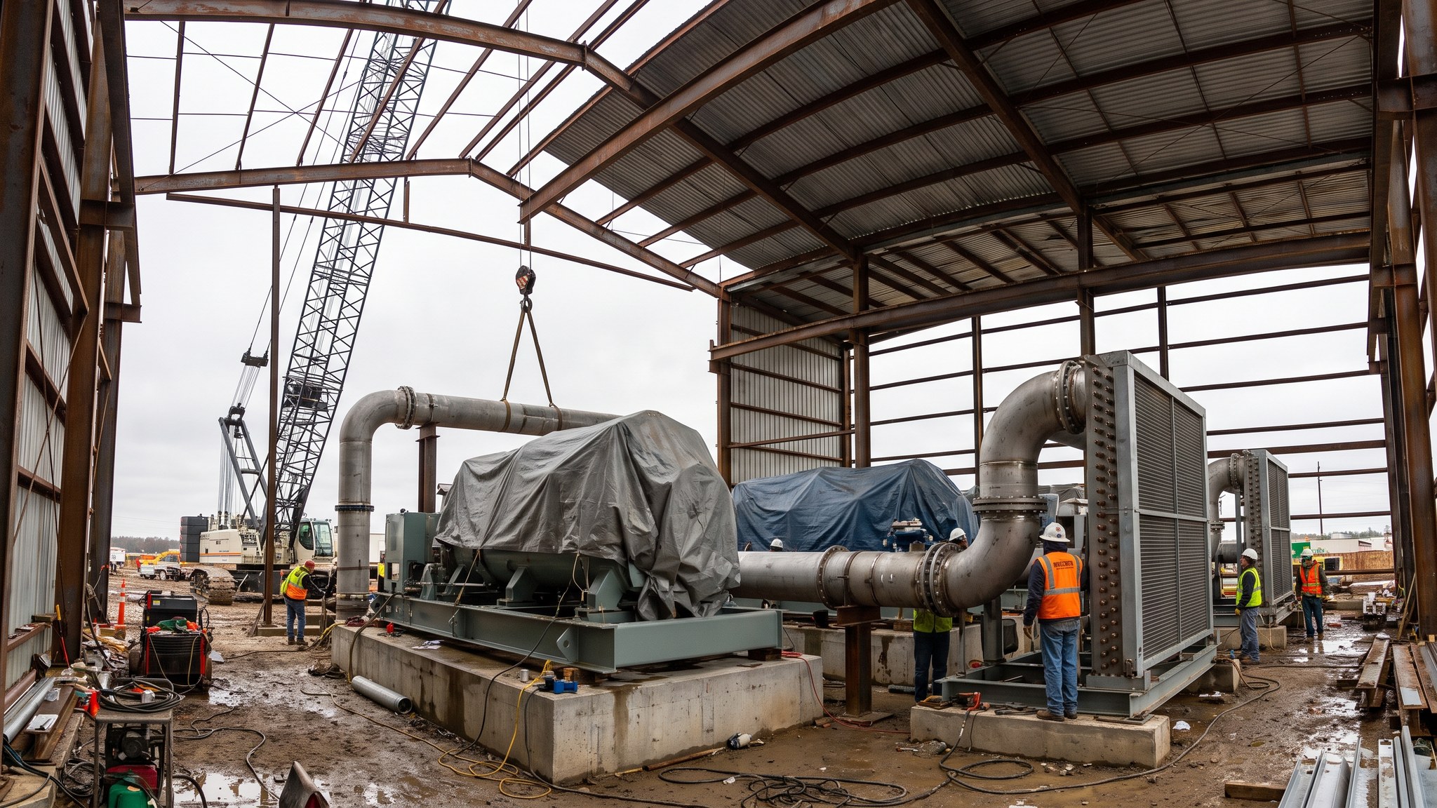
What is Reciprocating compression?
A reciprocating compressor raises the state of the gas by trapping it in a cylinder and squeezing it with a piston. It is an old and very well understood machine, and on a carbon capture project it occupies the part of the range where a centrifugal train does not do well. Where the flow is modest, where it varies through the day, or where a single stage has to achieve a large ratio, the reciprocating machine is comfortable and the centrifugal machine is not. It also holds its efficiency across a wide turndown, because capacity can be adjusted by unloading cylinder ends or by varying speed rather than by recycling gas around the machine and wasting the work already done on it.
The price is paid in mechanical complexity and in what the machine does to everything around it. A reciprocating compressor has pistons, rods, crossheads, valves and packing, all of which wear and all of which are on a maintenance schedule. It draws and discharges in pulses rather than in a smooth stream, and those pulses travel into the connected pipework as pressure waves. Left alone they shake pipe supports, crack small-bore connections and fatigue welds. Controlling them is a design exercise carried out before the pipework is fabricated - the designer studies the pulsation and the mechanical response of the piping system, and the outcome is bottles, restrictions, supports and a routing that the site is not free to change. On a carbon dioxide duty there is a further constraint: the machine must not let the process stream and the lubrication meet in ways the specification does not allow, so the sealing and lubrication arrangement is a specified item rather than a supplier default.
On site the reciprocating machine tends to be a smaller, more numerous, more flexible item than a geared train. Several machines can be installed in parallel so that capacity is added in steps and one machine can be taken off for maintenance without stopping export. The foundation demands are different but no lighter: the unbalanced forces and moments from the running gear go into the block, and the structural engineer designs for them using the supplier's data. What the operator gets in return is a machine that will follow a capture plant that ramps, and a machine that can be worked on in place by a competent maintenance team rather than by a specialist overhaul contractor.
How does Reciprocating compression work, step by step?
- 1
Step 1: Establish that the duty genuinely suits a reciprocating machine
The decision is made on flow, on variability and on the ratio wanted from each stage. Industrial capture on a batch or campaign process, a smaller emitter feeding a shared network, a booster duty on a long line, or a ship loading terminal that works in cycles - these are the situations where the reciprocating machine wins. The designer compares it against a centrifugal option on efficiency across the real operating profile rather than at the design point alone, because the whole argument for the reciprocating machine is what happens away from the design point.
- 2
Step 2: Configure the stages, cylinders and capacity control
The machine is configured with the number of stages, the cylinder sizes and the capacity control method fixed together. Capacity is commonly adjusted by unloading cylinder ends, by clearance pockets, by varying driver speed, or by a combination. How the machine will be turned down is agreed with the operator at this point, because it changes the cylinder arrangement and the driver selection. Interstage cooling and liquid separation are configured at the same time, for the same reason as on any compression duty - heat has to come out and condensed water has to be removed before the next stage.
- 3
Step 3: Carry out the pulsation and mechanical response study
This is the step that distinguishes reciprocating installations from every other kind. Before the pipework is detailed, the designer models the pressure pulsations the machine will generate and the mechanical response of the piping and supporting steelwork to them. The study produces the pulsation dampeners, the orifice plates, the pipe routing and the support arrangement, and it produces them as requirements rather than suggestions. Site cannot re-route a line, move a support or add a small-bore connection afterwards without going back to the study. Ignoring this is the single most common cause of persistent vibration problems on reciprocating installations.
- 4
Step 4: Design and build the foundation for the unbalanced forces
The running gear produces unbalanced forces and moments that a rotating machine does not. The supplier issues those forces and the structural engineer designs the block or table to resist them and to sit well away from resonance with the machine's running speeds and their multiples. On poor ground the block goes on piles. The anchor bolt arrangement, the grout specification and the levelling method all come from the supplier's installation requirements and are followed exactly.
- 5
Step 5: Set the machine and install the specified pipework
The machine is landed, set, levelled, aligned to its driver and grouted. Crankshaft web deflection is measured as part of setting, because it shows whether the frame has been distorted by the foundation. Suction and discharge pipework is then fabricated and installed to the routing and support arrangement the pulsation study set, with the dampeners and any flow restrictions in the positions specified. Small-bore connections are minimised, braced and recorded, because they are where vibration failures start.
- 6
Step 6: Complete the auxiliaries, sealing and lubrication
Cylinder lubrication, packing and distance pieces are completed to the specification for the service. Carbon dioxide duty places its own requirements on the materials used in the sealing elements and on how the distance pieces are arranged, and those requirements come from the designer and the machine supplier together rather than from a standard catalogue arrangement. Cooling, oil systems and instrumentation are completed and flushed before the machine is turned.
- 7
Step 7: Commission, then measure the vibration in service
Commissioning follows the usual staged route - mechanical completion, auxiliaries, mechanical run, operation on process - with the addition of a vibration survey once the machine is running on duty. The survey checks the real installation against what the pulsation study predicted, on the pipework as well as on the machine. Where readings exceed the levels the study set, supports are modified and the survey repeated. That loop is closed before handover, not left as a snag.
- 8
Step 8: Hand over with a maintenance regime the operator can actually run
A reciprocating machine has consumable parts on a defined cycle - valves and packing in particular - and the operator inherits a spares holding and an inspection schedule alongside the machine. Where several machines run in parallel, the maintenance strategy is built around taking one out at a time while export continues. Access, lifting provision and a clean area for valve work are confirmed as built, because valve maintenance is routine and frequent rather than exceptional.
What are the benefits of Reciprocating compression?
- Holds efficiency across a wide turndown, so it follows a variable or intermittent capture plant
- Achieves a large ratio per stage, which suits duties a centrifugal machine cannot reach economically
- Capacity added in steps by installing several machines in parallel
- One machine can be maintained while the others keep the export running
- Well understood mechanically, and maintainable in place by a competent site team
- Smaller individual items, easier to transport and to lift on a constrained site
What are the limitations of Reciprocating compression?
- Generates pressure pulsations that must be designed out before the pipework is fabricated
- Unbalanced forces and moments make the foundation design more demanding than for a rotating machine
- More wearing parts, so more frequent maintenance and a larger spares holding
- Noise and vibration in the compressor house, with implications for the building and for neighbours
- Sealing and lubrication arrangements need specific attention on this service
- Multiple machines take more plot area in total than a single equivalent geared train
What is Reciprocating compression best suited for?
What plant does Reciprocating compression need?
- Reciprocating compressor frame, cylinders and running gear on a supplier-specified foundation
- Electric driver with starting and speed control equipment as configured
- Pulsation dampening bottles and any specified flow restrictions
- Interstage coolers and liquid separators with their collection and routing systems
- Cylinder lubrication, frame oil system, filtration and cooling
- Compressor house or weather enclosure with acoustic treatment and lifting provision
- Vibration survey instrumentation for commissioning and for periodic checks
How is Reciprocating compression quality-checked?
- Pulsation and mechanical response study completed before pipework fabrication, with its outputs treated as requirements
- Foundation designed to the supplier's unbalanced force data, with the design check for resonance recorded
- Crankshaft web deflection measured and recorded during setting
- Pipework routing, supports, dampeners and restrictions verified as built against the study
- Small-bore connections listed, braced and inspected
- Material certification for components in contact with the process stream, including packing and sealing elements
- Vibration survey carried out on the machine and the connected pipework in service, with any modifications closed out before handover
- Valve and packing maintenance schedule, spares holding and access arrangements confirmed at handover