Heavy reinforced mats and machinery bases
Stiff, heavy bases under rotating machinery, where vibration and alignment govern the design rather than bearing capacity.
Last updated 2026-09-06
What is Heavy reinforced mats and machinery bases?
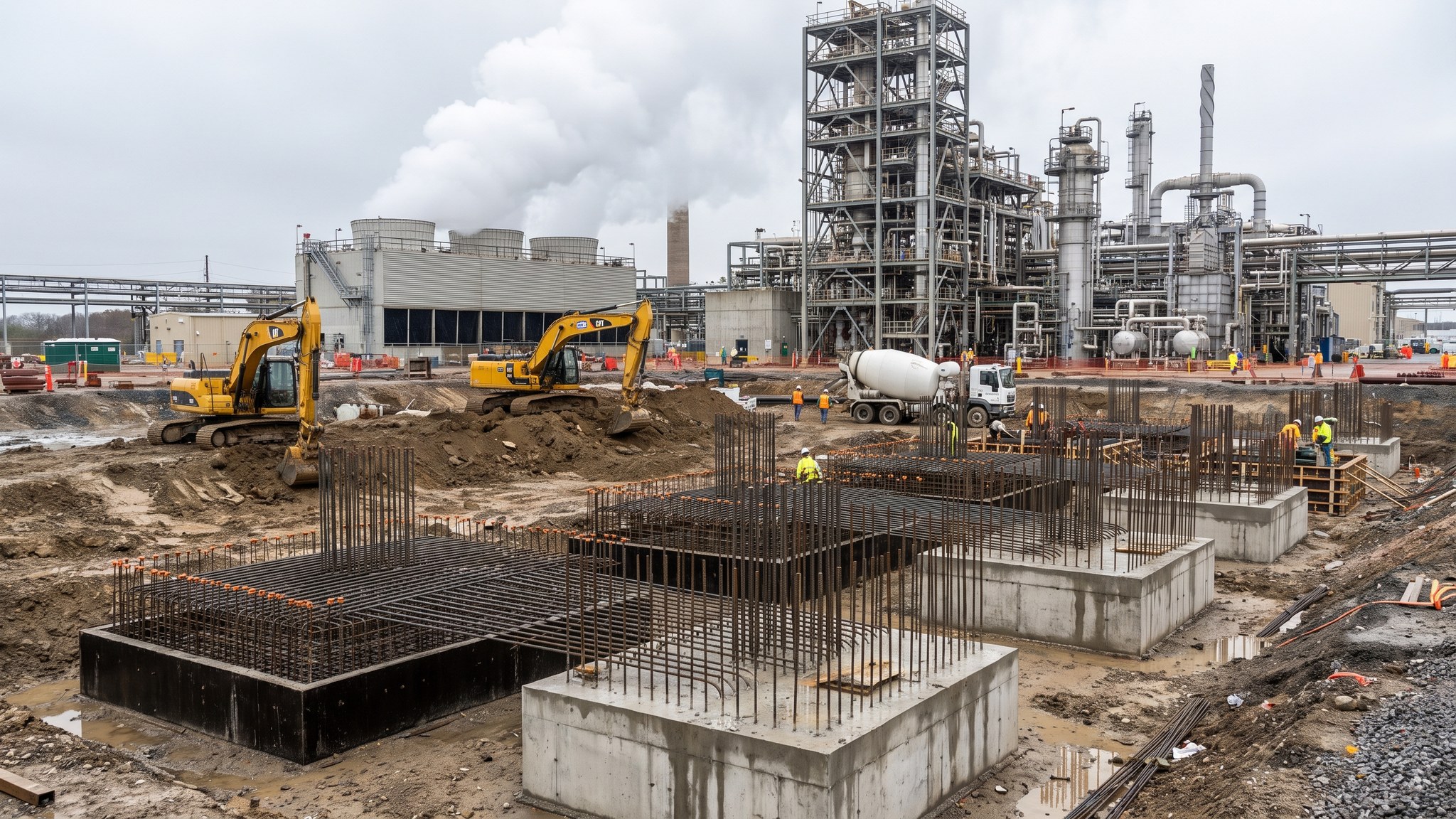
A capture plant runs on rotating machinery. Blowers, fans, compressors, pumps and their drives run continuously, and every one of them puts a dynamic load into whatever it is bolted to. The foundation under a machine like that is not sized by the weight of the machine. It is sized so that the base does not resonate with the machine, so that the machine stays in alignment over its life, and so that the vibration it produces is not transmitted into the structures and pipework around it. That is a different design problem from a normal foundation, and it usually produces a different answer: a heavy, deep, stiff reinforced concrete mat or block, often far larger than the footprint of the machine on it, sometimes isolated from the surrounding slab, and always designed with the machine supplier's data in hand.
The mass is doing real work. A heavy base lowers the natural frequency of the foundation and gives the dynamic forces somewhere to go, and stiffness keeps the machine and its driver in the relative position the supplier requires. Where the ground is poor, which on these sites it usually is, the mat sits on piles and the whole assembly - piles, cap and block - is designed together, because a stiff block on soft piles is not a stiff foundation. Where a machine is particularly sensitive, or particularly disruptive to what is near it, the designer may separate the base from the surrounding slab and structures entirely so that vibration does not travel. The specific arrangement for any machine on any project is the designer's decision, taken from the supplier data and the ground, and it is not something that can be read off a table.
The construction problem is tolerance. These bases carry holding-down bolt arrangements that have to match a machine skid to a fine tolerance across a base that may be several metres across, and the bolts have to be right in position, in level, in projection and in orientation. On most projects the arrangement is set with a purpose-made template supplied or approved by the machine supplier, surveyed before the pour, held rigidly through it, and surveyed again afterwards. Pockets and grout spaces are formed where the design allows the final position to be adjusted, and grouting under the machine base plate is a controlled operation in its own right, because the load path from the machine into the concrete goes through that grout and a void in it is a defect that only shows up as vibration months later.
How does Heavy reinforced mats and machinery bases work, step by step?
- 1
Step 1: Get the machine data before designing anything
The design starts with the supplier data for the specific machine: its mass and centre of gravity, the dynamic forces it produces, the frequencies it runs at and passes through, its alignment requirements, and the bolt arrangement it needs. Without that data the base cannot be designed, only guessed at. On most projects this is the first hard interface between the mechanical and civil packages, and late or changed machine data is the single most common cause of a foundation being redesigned after it has been drawn.
- 2
Step 2: Design the base and its support together
The designer sizes the block for stiffness and dynamic behaviour rather than for bearing alone, and designs the support beneath it in the same exercise - piles where the ground demands them, with the block and the piles considered as one system. Where the machine is sensitive or disruptive, isolation from the surrounding slab and structures is decided here. The result is usually a base far larger and heavier than the machine footprint suggests, and that size has consequences for the layout, the reinforcement and the pour, so it is settled early.
- 3
Step 3: Prepare the support and the formation
Piles are installed and trimmed, or the formation is prepared and proof-checked where the ground allows a direct bearing base. Blinding is placed and levelled. Where the design calls for the base to be separated from adjacent construction, the separation detail is formed at this stage rather than cut in later, because a separation joint that is bridged by a bit of concrete or a stray bar is not a separation joint.
- 4
Step 4: Fix the reinforcement and plan the pour
These bases are heavily reinforced and the steel is congested, particularly around bolt assemblies and pockets. The fixing sequence is planned so that the bolt template can be installed and adjusted, and so that concrete can actually reach the bottom of the block. Access for the poker crew is planned with the reinforcement, not after it. Where the pour is large, the designer sets how it is to be placed and whether it goes in one operation or in agreed lifts, and the specialist contractor plans supply, standby plant and labour to suit, because a large stiff base is a poor place to have an unplanned joint.
- 5
Step 5: Set the holding-down arrangement to the template
The bolt assemblies, sleeves or pockets are set using the template supplied or approved by the machine supplier, braced back to fixed points so that they cannot move, and surveyed for position, level, projection and orientation before any concrete arrives. Threads are protected. On most projects the surveyed record is signed by both the civils and mechanical teams before the pour is released, because after the pour the options narrow to shimming, re-drilling or breaking out.
- 6
Step 6: Pour, compact and cure with care
Concrete is placed to the agreed sequence and compacted properly around the reinforcement and the bolt assemblies - a poorly compacted zone under a machine base is exactly where the load is highest. The template is monitored during the pour so that any movement is caught while the concrete is still workable. Curing is controlled and protected, and on a thick block the designer will normally have set requirements about how the pour is managed as it hardens.
- 7
Step 7: Survey, prepare the bearing surface and hand over
Once the concrete has gained strength the base is surveyed against the model and against the supplier requirements, and the bearing surface is prepared as the design calls for - roughened, cut back or levelled - ready to receive the machine and its grout. Out-of-tolerance results go to the designer and the supplier together, because the acceptable remedy depends on the machine as much as on the concrete.
- 8
Step 8: Set the machine and grout the base plate
The machine or skid is set on the base, levelled and aligned to the supplier requirements on shims or levelling screws, and the space beneath the base plate is grouted as a controlled operation - formed, filled from one side so that air is pushed out rather than trapped, and left undisturbed while it cures. Alignment is checked again after grouting and after the machine has been run and reached its normal operating condition, because machines move as they warm through and the alignment that matters is the one at running condition, not the one in a cold workshop.
What are the benefits of Heavy reinforced mats and machinery bases?
- Mass and stiffness control the dynamic behaviour that a normal foundation would ignore
- Keeps rotating machinery in alignment over its operating life, which protects the machine as much as the structure
- Limits transmission of vibration into adjacent structures, pipework and instruments
- Can be isolated from the surrounding slab where the design requires it, containing the problem locally
- Provides a single well-defined interface for the machine supplier to work to
- Bolt pockets and grout spaces give the designer a controlled means of taking up setting-out tolerance
What are the limitations of Heavy reinforced mats and machinery bases?
- Cannot be designed without supplier data, so late or changed machine information forces redesign
- Much larger and heavier than the machine footprint suggests, which consumes plot space and concrete
- Heavily congested reinforcement makes proper compaction difficult and demands planning rather than improvisation
- Fine bolt tolerances across a large base are hard to hold through a pour and need templates and bracing
- Grouting under the base plate is a hidden operation where a void becomes a defect that appears only in service
- Large thick pours need supply, standby plant and a sequence agreed in advance
What is Heavy reinforced mats and machinery bases best suited for?
What plant does Heavy reinforced mats and machinery bases need?
- Piling and trimming plant where the base is piled
- Excavators and compaction plant for formation preparation and blinding
- Reinforcement handling and fixing equipment for congested heavy cages
- Formwork and falsework systems designed for deep lifts and the pressures they generate
- Concrete supply, pumping, vibration and curing equipment, with standby capacity for large pours
- Supplier templates, bracing steel, precise survey equipment, levelling shims and grouting equipment
How is Heavy reinforced mats and machinery bases quality-checked?
- Machine supplier data received and formally issued to the designer before the base is designed
- Reinforcement, cover and access for compaction inspected before the pour, with congested zones photographed
- Bolt template position, level, projection and orientation surveyed and signed off before concrete is released
- Template monitored during the pour and re-surveyed after it, with results issued to the mechanical package
- Concrete supply, placing and curing controlled to the agreed sequence, with the record kept per pour
- Grouting under the base plate carried out as a controlled operation, and alignment rechecked once the machine has reached normal running condition