Piled foundations with caps and ground beams
The normal answer on the reclaimed and industrial land these plants occupy - piles to a competent stratum, caps on top, ground beams tying the plot together.
Last updated 2026-09-06
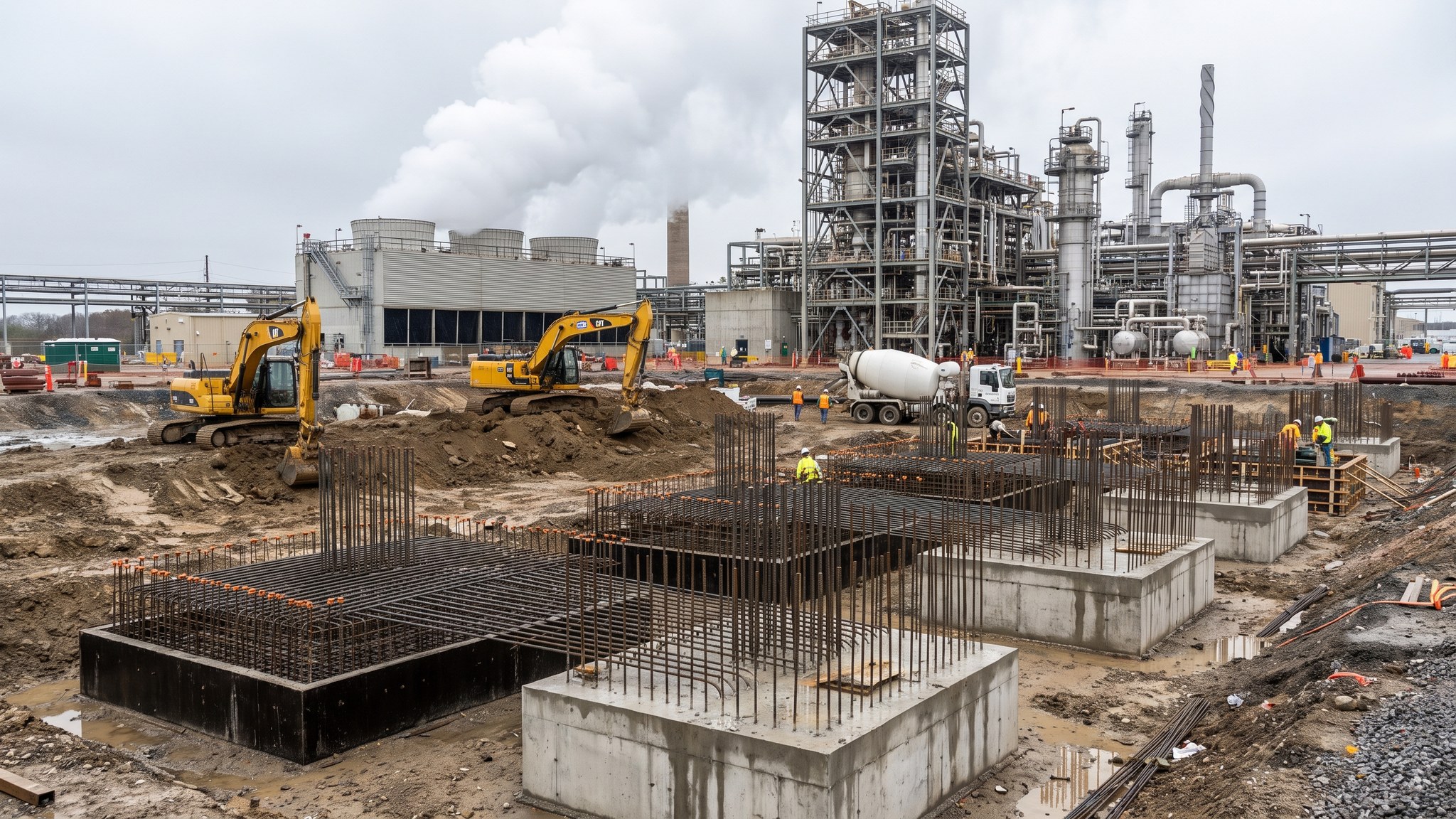
What is Piled foundations with caps and ground beams?
Capture plants are almost never built on good ground. They go where the emitting works already is, which on most projects means an estuary, a reclaimed dock, a former chemical or power site, or land that has been filled, dug over and filled again for a century. The made ground is deep, variable and full of old foundations, and the competent stratum sits well below it. So the foundations go down to that stratum on piles, the piles are capped, and the caps are tied together with ground beams into a single connected foundation system covering the whole plot. That is the standard solution and on most projects the designer reaches it early, because the alternatives - digging out and replacing, or spreading the load on shallow footings - stop working once the fill is more than a few metres thick and the loads start arriving from process equipment rather than from a building.
What makes this different from ordinary piled work is what sits on top. A capture plant is a dense field of separate structures at very different scales: tall columns, pumps and blowers, heat exchangers, tanks, pipe racks, electrical buildings, cable and drainage routes. Each has its own foundation, each has its own tolerance, and they all have to line up with each other because the pipework between them was drawn as a single system. The ground beams are what makes that possible. They tie the caps into a stiff plane, they carry the loads that fall between the equipment bases, and they give the mechanical and piping contractors a set of related datums rather than a scatter of independent islands. Where the designer allows it, the beams also carry the plinths, kerbs and bunds that come later, so the civils package is drawn as one connected thing rather than assembled from separate designs.
The programme pressure on this package is unusual. On a normal building the foundations are early and quiet. Here they are early and critical, because the module and column delivery dates were fixed long before the site started and the mechanical erection sequence cannot begin until the foundations for that area are complete, cured, surveyed and released. Piling that runs late does not delay the next civils operation - it delays a crane, a barge and a module that were booked a year in advance. So on most projects the piling sequence is set by the erection sequence rather than by the most efficient rig movement, the areas that receive the first modules are piled and capped first, and the specialist contractor works to a release-by-area programme with formal handover of each foundation to the mechanical team. That single fact governs how the work is planned, and getting it wrong is the most expensive mistake available on this package.
How does Piled foundations with caps and ground beams work, step by step?
- 1
Step 1: Establish what is actually under the plot
These sites have a history and the history is in the ground. The investigation covers the fill and its variability, the depth to a competent bearing stratum, the water level and its tidal response where the site is near water, and contamination, because on a former industrial site the arisings are a disposal problem before they are a spoil heap. Obstruction surveys matter as much as the boreholes: old foundations, basements, tanks, culverts and abandoned services are normal here, and a pile that refuses on a buried mass concrete block is a delay to the erection programme, not just to the rig. The designer sets the foundation strategy from that picture and the specialist contractor prices the risk of what the probes did not find.
- 2
Step 2: Fix the pile type and the layout against the plant layout
The pile type follows the ground, the loads and the setting. Displacement types suit granular fill where noise and vibration can be tolerated; bored and augered types suit sites where obstructions, neighbours or existing operating plant rule out driving. The layout follows the plant layout, not the other way round: every vessel, machine, rack leg and building gets its group, and the groups are set out against the same plant grid the mechanical designer works from. On most projects a single shared setting-out control network is established at this point and used by every trade for the rest of the project, because two networks on a process plant eventually produce two versions of where a column is.
- 3
Step 3: Clear obstructions and build the piling platform
Obstructions are located and removed or worked around before the rig arrives, and the platform is designed and certified in writing as a structure in its own right - piling rigs are tall, heavy and top-loaded, and on a reclaimed site they stand on the worst ground on the project. Access routes, crane stand areas and the later erection platform are all considered together at this stage, because on these projects the same ground has to serve the piling rig now and a very large crawler crane later, and it is cheaper to build it once to the higher standard.
- 4
Step 4: Install the piles to the agreed criteria
Preliminary piles are installed and tested first where the specification calls for them, and the production criteria come from those results. Each pile is then installed to the agreed depth or set, with the rig record kept pile by pile - position, depth, and the installation parameters the specification lists. Piles that refuse short, that come up out of tolerance, or that behave unlike their neighbours are reported to the designer rather than absorbed on site. On a plant site with a hundred separate foundations, the pattern across a group tells you more than any single record.
- 5
Step 5: Trim, cap and tie the plot together
Pile heads are cut down to level, the reinforcement is exposed and cleaned, and the caps are formed, reinforced and poured. Ground beams follow, spanning between the caps and tying the caps into a connected system. Reinforcement congestion at the cap and beam junctions is a real buildability problem here and is normally resolved by the designer on a drawing before it is discovered by a steel fixer at seven in the morning. Concrete for these elements is placed to a pour sequence agreed in advance, because a plant site does not have room for everything to be poured at once and the sequence has to leave access for the next pour.
- 6
Step 6: Set the interfaces the mechanical package will use
The value of a foundation on a process plant is measured at its interface. Holding-down bolt assemblies, pockets, base plates and levelling arrangements are set to the tolerances the specification gives, checked before the pour and checked again after it, and their positions are recorded against the shared control network. Anything the equipment supplier has fixed - a bolt circle, a plinth level, an orientation - is treated as fixed. The recurring failure on these projects is not a weak foundation. It is a foundation in the wrong place by a few tens of millimetres, discovered when a module is hanging on a crane.
- 7
Step 7: Cure, survey and release area by area
Concrete is cured and protected, then each foundation is surveyed and compared against the model. Out-of-tolerance items are resolved with the designer and the equipment supplier before the area is released, because the resolution may be a shim, a re-drill, a change to the module or a re-pour, and only one of those is quick. Areas are handed over formally in the sequence the erection programme needs, with a record of what was released and when.
- 8
Step 8: Protect the finished work through the mechanical campaign
Once the foundations are released the site fills with cranes, transport, scaffold and hundreds of people. Bolt threads are protected, pockets are covered, edges are protected from tracked plant, and the survey control is protected from being knocked. On most projects the civils contractor stays on site through erection to maintain the foundations, the platform and the temporary works, because the plot is in continuous heavy use for months and left alone it degrades quickly.
What are the benefits of Piled foundations with caps and ground beams?
- Carries load through deep and variable made ground to a competent stratum, which is the normal condition on these sites
- Ground beams tie the whole plot into one connected system, giving the mechanical trades related datums rather than isolated islands
- Copes with the very wide range of load types on a process plant, from light rack legs to heavy vessels, within a single foundation strategy
- Allows foundations to be sequenced and released area by area to match the module and column delivery programme
- Reduces the volume of contaminated arisings compared with digging out and replacing deep fill
- Well understood by the UK supply chain, so the risk sits mostly in the ground rather than in the method
What are the limitations of Piled foundations with caps and ground beams?
- Obstructions in old industrial fill cause refusals, redesign and delay, and no investigation finds all of them
- Driven types generate noise and vibration that may be unacceptable next to an operating works or to neighbours
- Bored types generate arisings that on a contaminated site are a significant disposal cost
- The package is on the critical path in a way ordinary building foundations are not, because it gates crane and module dates
- Congested reinforcement at cap and beam junctions is a buildability risk that has to be designed out rather than solved on site
- Requires a designed and maintained working platform that then has to serve heavy erection cranes as well
What is Piled foundations with caps and ground beams best suited for?
What plant does Piled foundations with caps and ground beams need?
- Piling rigs of the type suited to the ground - driven, bored or augered - with their ancillary equipment
- Obstruction removal plant: large excavators, breakers and grabs
- Dozers, rollers and graders for the designed working platform
- Concrete supply, placing and pumping plant, with vibration and finishing equipment
- Reinforcement handling and fixing gear, and formwork systems for caps and beams
- Survey equipment tied to a single site-wide control network, with load testing equipment for the pile testing regime
How is Piled foundations with caps and ground beams quality-checked?
- Working platform designed, certified in writing and re-inspected as rig and crane traffic changes it
- Pile testing regime agreed before mobilisation and completed to the specification
- Installation record per pile, with refusals and anomalies reported to the designer rather than absorbed
- Reinforcement, cover and holding-down arrangements inspected and photographed before every pour
- Post-pour survey of every foundation interface against the model, with a signed out-of-tolerance route to the designer and the equipment supplier
- Formal area-by-area handover record to the mechanical package, and protection of released foundations thereafter
More site civils & heavy foundations methods
Next method
Heavy reinforced mats and machinery bases