Piled pipe rack and module support lines
Long lines of foundations carrying the racks and modules, where setting-out accuracy over hundreds of metres decides whether the modules fit.
Last updated 2026-09-06
What is Piled pipe rack and module support lines?
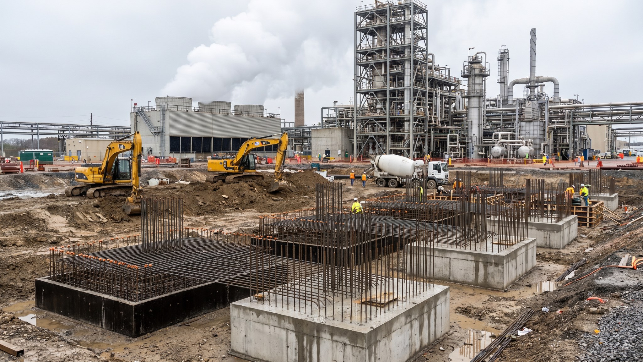
A capture plant is stitched together by pipe racks. They run from the emitting works to the capture island, through the plant and out to the compression and export end, carrying process lines, utilities, cabling and access walkways, and they are supported on long lines of foundations - typically a repeating arrangement of piled bases at regular centres running for hundreds of metres. The same is true of the support lines under large modules, which land on prepared foundations set out in a pattern fixed by the fabricator months earlier. Individually these are simple foundations. Collectively they are the hardest setting-out problem on the project, because the accuracy that matters is not the accuracy of any one base but the accumulated accuracy along the whole line.
That distinction is the whole point of this variant. A base that is a few millimetres out is nothing. A line of forty bases that drifts steadily in one direction is a rack that will not fit, or a module that lands on three of its four supports. Modules and racks are fabricated to their own tolerances in a yard against a drawing, and they do not adjust to the ground. So the discipline on these lines is different from ordinary foundation work: one control network for the whole site, control points protected and re-checked, every base surveyed against the model rather than against its neighbour, and an out-of-tolerance route that goes to the designer and the fabricator together rather than being closed out on site.
The other governing factor is the programme. Rack and module support lines run across the plot and therefore across every other trade, and they are needed early because the racks go up before much of the equipment and because the modules arrive on dates fixed long in advance. On most projects the lines are built in the sequence the erection programme demands, released area by area, and then protected while the rest of the site works around them. They also have to accommodate what runs beneath and beside them - drainage, buried services, cable routes, access roads - so the coordination effort is out of proportion to the apparent simplicity of the concrete.
How does Piled pipe rack and module support lines work, step by step?
- 1
Step 1: Establish one control network and defend it
A single primary control network is established across the whole plot and used by every trade, tied to the plant grid the mechanical designer works to. Control points are placed where they will survive the works, physically protected, and re-checked on a set frequency. On a site this size, control is the foundation under the foundations: two networks, or one network that has been knocked by a dumper and never re-checked, is how a rack line drifts.
- 2
Step 2: Coordinate the line against everything it crosses
Before the bases are set out, the line is coordinated against underground drainage, buried services, cable routes, roads, other foundations and future access. Clashes are resolved on a model with the designer, not with a breaker on site. Rack lines cross the whole plot and therefore cross the whole project, so this coordination is done once, properly, and reissued when anything moves.
- 3
Step 3: Take the fabricator arrangement as fixed
The rack and module support arrangement comes from the fabricator: the centres, the base plate arrangement, the bolt pattern, the levels and the permitted tolerances. Those are treated as fixed inputs, and where the civil design cannot achieve them the difference is raised with the fabricator before construction rather than discovered at delivery. On most projects the tolerance the fabricator quotes is tighter than a civils team would expect, and it is quoted for a reason.
- 4
Step 4: Pile the line to the sequence the erection needs
Piles are installed along the line in the sequence the erection programme requires, with the rig record kept per pile and refusals or anomalies reported to the designer. Because the line is long, the rig moves continuously and the temptation is to set out ahead in long runs from a single station - which is exactly how accumulated error appears. Setting out is re-established from primary control at intervals rather than chained along the line.
- 5
Step 5: Trim, cap and set the interface to the model
Pile heads are trimmed, caps and plinths are formed and reinforced, and the holding-down arrangement for each rack leg or module support is set using a template, braced rigidly, and surveyed for position, level, projection and orientation against the model before the pour. Threads and pockets are protected. This is the same discipline as a machine base, applied to dozens of repetitive positions, and repetition is where discipline usually slips.
- 6
Step 6: Survey the whole line, not just the bases
After curing, every base is surveyed against the model and the results are looked at as a line rather than as individual records. A drift, a systematic offset or a rotation across a run of bases is the finding that matters, and it is only visible when the results are plotted together. Where an out-of-tolerance condition is found, the designer and the fabricator agree the remedy together - a shim, a modified connection, a re-drill or a re-pour - and the decision is recorded.
- 7
Step 7: Release the line and protect it
The line is handed over formally to the steelwork or mechanical package, with the as-built survey issued so that the erection team works from measured positions rather than drawn ones. The bases are then protected: threads capped, pockets covered, edges guarded from tracked plant, and control points defended. A rack line crossing an active site is in the way of everything, and unprotected it will be damaged.
- 8
Step 8: Support the erection and close out the interfaces
During erection the civils team stays available to resolve what the survey did not catch, to make good, and to complete the associated works - plinths, kerbs, drainage, cable routes and surfacing - once the racks and modules are in place and access allows. Closing out these interfaces after erection rather than before is normal on process plant, and planning for it avoids a second mobilisation.
What are the benefits of Piled pipe rack and module support lines?
- Repetitive, efficient foundation work that suits continuous rig and pour production once the line is set out
- Carries rack and module loads through poor fill to a competent stratum along the whole route
- A single control network gives the erection team measured positions to work from, not assumed ones
- Allows racks to be erected early, opening up the plant for pipework and cabling ahead of equipment
- Sequenced release by area matches the fixed module and column delivery dates
- Standardised details across many positions reduce design effort and error once they are agreed
What are the limitations of Piled pipe rack and module support lines?
- Accumulated setting-out error over hundreds of metres is the dominant risk and is invisible base by base
- Fabricator tolerances are tighter than ordinary civils tolerances and leave little room for site adjustment
- The lines cross the whole plot, so coordination with services, drainage and roads is heavy
- Damage from other trades is near certain without active protection of bases and control points
- Late changes by the fabricator ripple along the entire line rather than affecting one base
- Associated works around the bases usually cannot be completed until after erection, requiring a return visit
What is Piled pipe rack and module support lines best suited for?
What plant does Piled pipe rack and module support lines need?
- Piling rigs suited to the ground, working in continuous linear production
- Excavators for trimming, cap excavation and associated buried works
- Reinforcement and formwork systems standardised across repeating base types
- Concrete supply and placing plant able to serve a moving front across the plot
- Templates and bracing for repeated holding-down arrangements
- Precise survey equipment tied to protected primary control, with as-built recording capability
How is Piled pipe rack and module support lines quality-checked?
- Primary control network established, protected and re-checked on a set frequency
- Fabricator arrangement and tolerances formally received and used as the design basis
- Setting-out re-established from primary control at intervals rather than chained along the line
- Template position, level, projection and orientation surveyed and signed off before every pour
- As-built survey of the whole line reviewed as a set to detect drift, offset or rotation, not just base by base
- Formal handover of each released run to the erection package, with as-built data issued and physical protection in place