Ductwork installation
Sheet metal air routes hung above the ceiling - the biggest services element on the project, and the one everything else has to fit around.
Last updated 2026-09-05
What is Ductwork installation?
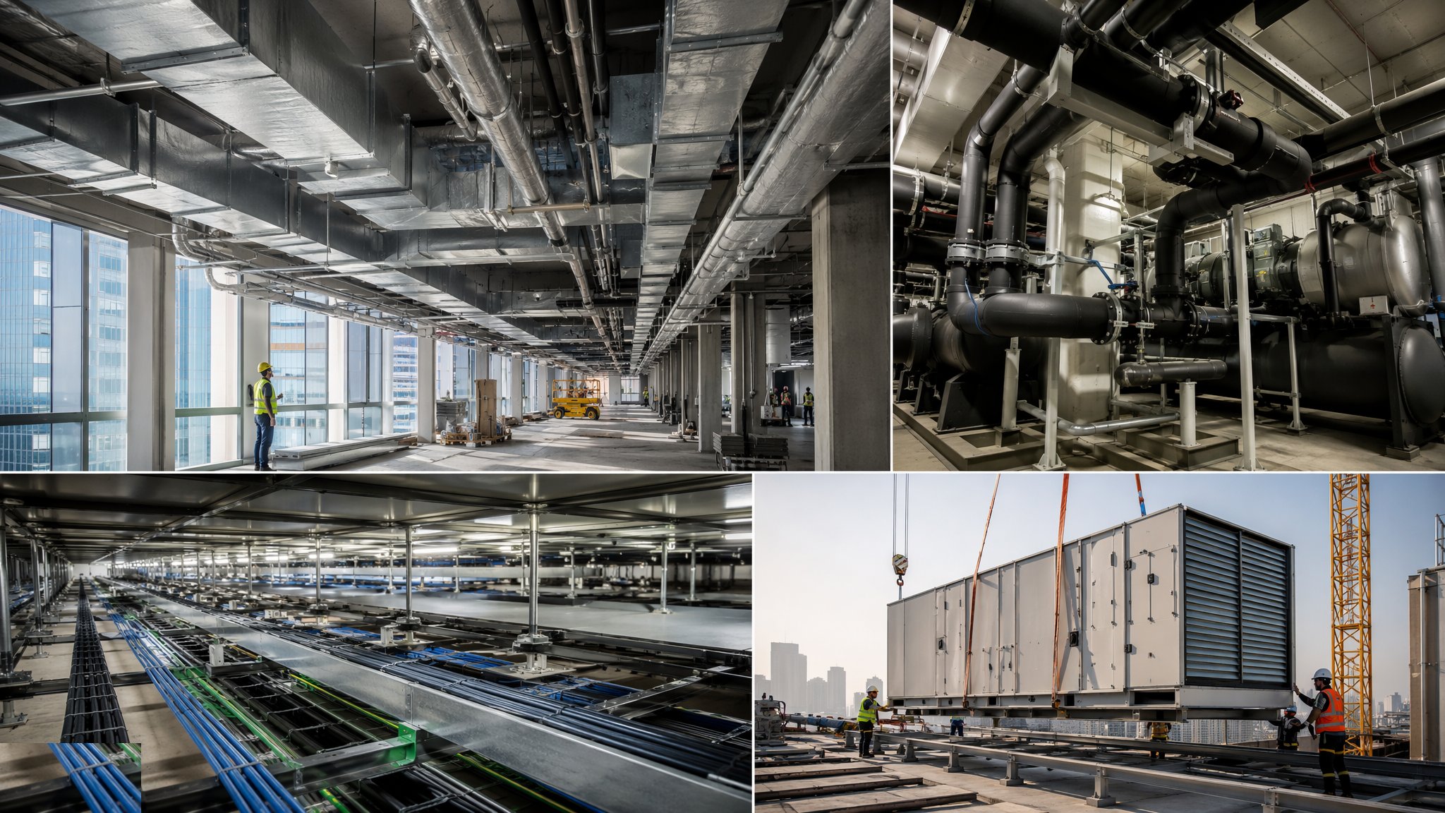
Ductwork is how conditioned air gets from the plant to the people and how stale air gets back out again. It is fabricated sheet metal, usually galvanised steel, formed into rectangular, circular or flat oval sections and joined into a continuous run from the air handling unit to the terminals in the occupied space. On most commercial projects it is the largest single services element by volume - far bulkier than pipework, cable containment or sprinkler mains - which is why it takes first claim on the ceiling void and why every other trade routes around it. The specialist ductwork contractor works to the services engineer's design: the engineer sizes the system for the air it has to move and the noise and energy limits it has to meet, and the contractor turns that into a fabrication schedule, a set of supports and an installation sequence.
Very little of a modern duct system is made on site. Sections are fabricated off site on coil lines and folding plant, flanged or spigotted ready for jointing, labelled to a drawing reference and delivered in the order the installation programme needs them. That off-site model is what makes ductwork fast on site, and it is also what makes it unforgiving: a duct run that was set out from a superseded drawing arrives as a lorry load of metal that does not fit anything. The remedy is a coordinated services model, agreed and frozen before fabrication is released, in which the ductwork, pipework, cable containment, sprinklers, structure and the ceiling itself all occupy space that has been allocated to them rather than space they claimed first.
Three things then decide whether the installed system performs. The first is support - duct is light for its size but it is a long, hung, air-filled structure, and the supports and hangers are a designed element, not an afterthought at the end of a drop rod. The second is the treatment at compartment lines, where fire dampers and their builder's work openings keep the duct from turning a fire barrier into a chimney. The third is airtightness: duct leaks at joints, and leakage is measured and accepted against the specification rather than assumed. Insulation, access panels for cleaning and the identification of each run complete the package before ceilings close.
How does Ductwork installation work, step by step?
- 1
Step 1: Coordinate the route before anything is ordered
The starting point is a coordinated services model that shows the ductwork against the structure, the pipework, the containment, the sprinkler system, the lighting and the finished ceiling line. Ductwork usually takes priority in that model because it is the biggest and the least bendable, but the priority is agreed rather than assumed. Every penetration through a wall, floor or beam is identified and issued to the structural designer as a builder's work item, because a hole cut later without approval is a structural problem as well as a services one. On most projects this coordination stage is the single largest programme risk in the mechanical package - a clash found in the model costs a drawing revision, and the same clash found above a ceiling costs a section of duct, a scaffold, a delay to the ceiling contractor and an argument.
- 2
Step 2: Fabricate off site to the released drawings
Once the model is frozen, fabrication is released. Rectangular duct is cut, folded and joined into sections with a flanged jointing system; circular duct is rolled or bought as spiral-wound tube with fittings; flat oval sits between the two and is used where the void is shallow but the airflow suits a round profile. Each section is marked with its drawing reference and its position in the run, and delivered in sequence. Sealants and gaskets are selected against the duct classification the designer has specified, and the fabricator works to the tolerances and stiffening arrangements that classification calls for. Changing anything after release means changing it in the model first and then in the shop - never on the floor with an angle grinder.
- 3
Step 3: Set out and install the supports
Support positions are set out from the coordinated drawings before any duct goes up, and the supports are installed as a system: drop rods or threaded hangers fixed into the structure, bearers under the duct, and anti-vibration provision where the design calls for it. Spacing, bearer size and fixing type all come from the specification and the supplier's support design against the duct size and weight, not from what looks about right. Fixings into concrete are proof-tested where the specification requires it. Long horizontal runs, vertical risers and anything carrying insulation and cladding on top of the metal are all separate support cases, and the risers in particular need support at the floor structure rather than hanging off the run below.
- 4
Step 4: Erect the runs and make the joints
Duct sections are lifted into the supports and jointed working from the plant outwards, so that the main runs establish the level and the branches pick up from them. Joints are pulled up with the specified cleats or clamps, gasketted or sealed, and checked as they are made - a joint above a ceiling that is already boarded is not going to be improved later. Open ends are capped at the end of every shift, both to keep the system clean and to stop the run becoming a rubbish chute for the following trades. Flexible connections go in at plant items so the fan does not shake the duct system, and terminal connections are left off until the ceiling grid is set out.
- 5
Step 5: Fit fire dampers, access panels and insulation
Wherever a duct crosses a fire compartment line, a damper is installed in the wall or floor construction in the arrangement the fire strategy and the damper manufacturer require, with its builder's work opening made good around it and its position recorded. Access panels are fitted at the positions the designer has scheduled - at dampers, at fans, at attenuators and at intervals along runs so that the system can be inspected and cleaned in service. Panels above a ceiling are worthless if the ceiling has no matching access, so the panel positions are coordinated with the ceiling contractor. Thermal and acoustic insulation, and any external cladding, then go on to the completed and inspected metalwork.
- 6
Step 6: Test for leakage and clean the system
Ductwork leaks, and the specification states how much leakage is acceptable for the class of duct installed. Testing is carried out on sections as they are completed rather than on the whole system at the end, so that a failure can be traced to a manageable length of run and put right while access still exists. The specialist contractor pressurises the sealed section with a test fan and measures the flow needed to hold pressure, and the result is assessed against the criteria the designer set. The system is then cleaned to the standard of cleanliness the specification calls for, sealed, and handed to the commissioning team.
- 7
Step 7: Balance, commission and record
With terminals fitted and the ceiling in, the commissioning engineer sets the dampers and terminal devices so that each part of the system delivers the airflow the design intends, and records what was achieved against what was specified. Fire dampers are proved to operate and their positions and references are logged. The record package handed over includes as-installed drawings, the duct classification, the leakage test results, the damper schedule with locations, the balancing figures and the cleaning report. On a building that will be maintained for decades, an accurate damper and access panel schedule is worth more than almost anything else in the file.
What are the benefits of Ductwork installation?
- Off-site fabrication turns a slow sheet metal trade into a fast install-and-joint operation on site
- Rectangular, circular and flat oval profiles give the designer options where the ceiling void is tight
- Galvanised steel systems are durable, cleanable and repairable over a long building life
- Circular and spiral-wound duct is inherently stiffer and generally tighter than rectangular for the same duty
- A coordinated model lets the whole services package be sequenced around the ductwork rather than discovering it above the ceiling
- Sectional leakage testing gives measurable evidence of quality as the work proceeds
What are the limitations of Ductwork installation?
- The bulkiest services element on most projects - it drives the ceiling void depth and therefore the floor-to-floor height
- Clashes above a ceiling are the classic programme killer, and they are usually found by the trade that arrives last
- Fabricated off site to frozen drawings, so late design changes are expensive rather than merely inconvenient
- Fire dampers add builder's work openings, coordination with the fire strategy and a permanent maintenance access obligation
- Working at height above ceilings for long periods, with the access and edge protection burden that brings
- Poor jointing and support workmanship shows up as leakage, noise and sag, and is largely hidden once the ceiling is boarded
What is Ductwork installation best suited for?
What plant does Ductwork installation need?
- Off-site fabrication capability - coil line, folding and rolling plant, and a flanged or spigotted jointing system
- Delivery and lifting arrangements suited to long sections, including scissor lifts and mobile access platforms
- Support and hanger components, drop rods, bearers and structural fixings with a proof-testing capability
- Sealants, gaskets and jointing components matched to the specified duct classification
- Duct leakage test rig - test fan, flow measurement and blanking-off equipment
- Insulation and cladding materials, access panels, fire dampers and their fixing frames
- Cleaning and inspection equipment, and airflow measurement instruments for balancing
How is Ductwork installation quality-checked?
- Coordinated services model signed off and frozen before fabrication is released
- Builder's work openings agreed with the structural designer before any penetration is formed
- Support positions, bearer sizes and fixing types installed to the support design, with fixings proof-tested where specified
- Duct classification, sealants and gaskets checked on delivery against the specification
- Sectional leakage testing as work proceeds, with results recorded and assessed against the specified criteria
- Fire damper positions, references and operation recorded, with matching ceiling access provided and checked
- System cleanliness inspected and recorded before ceilings close, and open ends capped at the end of every shift
- Commissioning and balancing results issued with as-installed drawings and the damper and access panel schedule
More commercial mep & vertical distribution methods
Next method
Lift installation