Four-pipe fan coil systems
Separate heating and cooling water to every unit, so one part of the floor can be warming while the next is cooling.
Last updated 2026-09-05
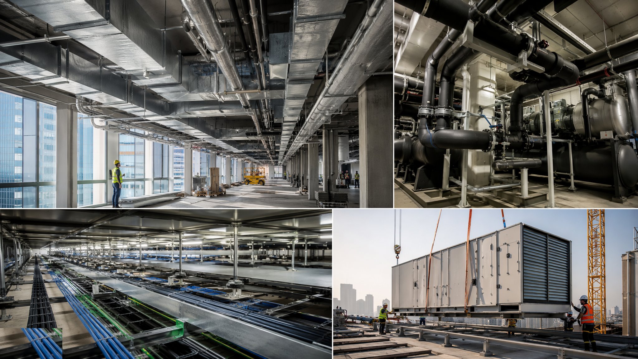
What is Four-pipe fan coil systems?
A four-pipe fan coil system runs two water circuits around the building instead of one. Chilled water flows in one flow and return pair, low temperature hot water in the other, and every fan coil unit on the floor has a coil fed from each. That is the whole point of the arrangement. A meeting room full of people on the south face can be calling for cooling at the same moment as a corner office on the north face is calling for heat, and neither has to wait for the plant to change over. On most commercial projects the units sit in the ceiling void above the corridor or the perimeter, ducted a short distance to supply grilles or slot diffusers in the ceiling, drawing return air through the void or through a return grille. Fresh air is handled separately, usually by a central air handling unit delivering treated outside air into the same distribution, so the fan coils are dealing with the room load and the air handling plant is dealing with the ventilation.
The attraction for a landlord and for a tenant is local control. Each unit, or each small group of units, serves a zone with its own controller, so the floor can be divided and redivided as tenants take space and change their layouts. Add a partition and you move a controller and a couple of grilles rather than rebuild a riser. That flexibility is why fan coils have been the default on speculative offices for a long time. The trade is that the floor is full of small machines. Every unit has a fan, filters, two coils, control valves and a condensate connection, and every one of those needs to be reachable for the rest of the life of the building. On a large floor plate that can be a lot of units sitting above a ceiling that somebody has to be able to open.
The decision between fan coils and the alternatives is normally settled by three things: how divisible the floor has to be, how much ceiling void the structure leaves, and who is going to maintain it. Fan coils need less riser space and less plant room than a fully centralised air system because most of the heat is moved in water rather than in air, and water moves heat in a much smaller pipe than air does in a duct. They cost more to keep running properly, because filters, condensate and bearings are a recurring commitment across a large population of units. The services engineer decides the arrangement for a particular building from the loads, the facade, the void depth and the way the space is expected to be let. What the site team needs to know is that this is a wet system in the ceiling, above finished space, distributed everywhere.
How does Four-pipe fan coil systems work, step by step?
- 1
Step 1: Set the zoning with the letting strategy
Before a single unit is positioned, the designer and the landlord agree how the floor might be split. A floor that could let as one occupier, as two halves or as four suites has to be zoned and valved so that each of those splits works without cutting into live pipework later. That drives the number of units, where the control zones sit and where isolation valves and drain points go on each branch. Getting this wrong is not a technical failure on day one, it is an expensive alteration on the first tenant change.
- 2
Step 2: Prove the ceiling void will take it
The unit, its two coils, the pipework with insulation, the condensate falling away to a drain, the ducted supply and the lighting all have to coexist in the space between the underside of the structure and the top of the ceiling. That coordination is done in the model before anything is ordered. On most projects the perimeter zone and the crossing points at beams and downstand edges are the tight spots. The team walks the model looking for the places where the pipe has to cross the duct, because those are the places that stop the job on site.
- 3
Step 3: Install the risers and the main horizontal distribution
Flow and return for both circuits are taken up the riser and out along the floor on the main runs, usually in the corridor zone where the void is deepest and access is easiest. Brackets and supports are set out to the spacing the specification requires, guides and anchors are fixed where the designer has shown them so the pipe expands where it is meant to, and the insulation and vapour sealing on the chilled lines is continuous. A break in the vapour seal on a chilled line is not a small defect. It condenses inside the insulation and the first sign of it is a stain on somebody's ceiling tile a year after handover.
- 4
Step 4: Set and connect the units
Units are hung on drop rods with anti-vibration mounts, levelled, and set at a height that keeps the condensate tray falling the whole way to the drain. Branches are taken off the mains with isolation and regulating valves at each unit so the unit can be dropped out later without draining the floor. Flexible connections take the last short length into the unit. Every unit is labelled to the same reference the model, the commissioning schedule and the maintenance records use, because a ceiling full of identical white boxes with no labels is a maintenance problem for the next thirty years.
- 5
Step 5: Run the condensate and prove it falls
Fan coils make water whenever they cool. The condensate drain is the part of the installation most often rushed and most often the cause of damage. Trays are checked for fall, pipe runs are laid to a continuous gradient to the point the designer has nominated, traps are formed and filled, and pumped condensate is used only where the fall cannot be achieved. Every drain is tested by filling the tray with water and watching where it goes before the ceiling is closed. On most projects this is the single cheapest test on the floor and the one that saves the most money.
- 6
Step 6: Flush, fill and pressure test both circuits
The pipework is flushed to remove the debris that installation always leaves, chemically cleaned, dosed with the inhibitor the specification calls for and pressure tested before the ceiling closes. Both circuits are done, and the chilled circuit is tested with its insulation arrangement understood so the joints are still accessible. Water samples are taken and recorded. The test certificate covers the section it was actually run on, not the floor in general, and any section altered after test is retested rather than assumed.
- 7
Step 7: Balance, commission and set the controls
Water side balancing sets the flow through every unit to the design figure and records it. Air side balancing sets the supply and return at every grille. Then the controls are commissioned: sensors proved in the right rooms, valves proved to open and close in the right direction, zone controllers proved against the zone they actually serve and not the one on the drawing. Mislabelled control zones are the classic fan coil defect, and they are only ever found by walking the floor with one zone driven at a time. Records, an as-installed set of drawings and the maintenance access strategy are handed over together.
What are the benefits of Four-pipe fan coil systems?
- Simultaneous heating and cooling across the floor, so opposite facades and internal rooms are all satisfied at once
- Good local control, with zones that can be re-cut as tenants take and change space
- Smaller risers and less plant room than an all-air system, because most of the heat is moved in water
- Units can be added, moved or isolated one at a time without shutting the floor down, if the valving was set out for it
- A well understood arrangement that most contractors, commissioning engineers and facilities teams already know
- Suits speculative offices where the eventual occupier and layout are unknown at the time of building
What are the limitations of Four-pipe fan coil systems?
- A large population of small machines above the ceiling, all with filters, bearings and condensate to maintain
- Access panels are needed wherever a unit sits, which constrains the ceiling design and the lighting layout
- Condensate is present above finished space everywhere, so a poor drain detail becomes visible damage
- Two circuits means more pipe, more insulation and more coordination in the void than a changeover system
- Fan noise at the ceiling is a real acoustic constraint in quiet spaces and needs to be designed for, not discovered
- Chilled pipework insulation and vapour sealing must be continuous, and site damage to it is easy and consequential
What is Four-pipe fan coil systems best suited for?
What plant does Four-pipe fan coil systems need?
- Fan coil units with their mounts, drop rods and anti-vibration fixings
- Pipe fabrication and jointing equipment for the two circuits, with supports, guides and anchors
- Insulation and vapour sealing materials for chilled flow and return, with the tools to finish penetrations
- Flushing and chemical cleaning rig, dosing equipment and pressure test kit
- Water side balancing instruments and air side flow measuring equipment
- Access equipment for working at ceiling level over a whole floor plate, and lifting aids for setting units
How is Four-pipe fan coil systems quality-checked?
- Coordinated void model signed off before ordering, with the tight crossings resolved
- Every condensate tray and drain water tested and witnessed before the ceiling is closed
- Pressure test and flushing certificates issued section by section, with water samples recorded
- Chilled pipework insulation and vapour seal inspected continuous, including at supports and penetrations
- Water and air balancing results recorded per unit and per grille against the design schedule
- Control zones proved by driving one zone at a time and walking the floor, with unit labelling matched to the records