VRF/VRV direct expansion
Refrigerant piped from an outdoor unit to indoor units, with no water and no wet services on the floor.
Last updated 2026-09-05
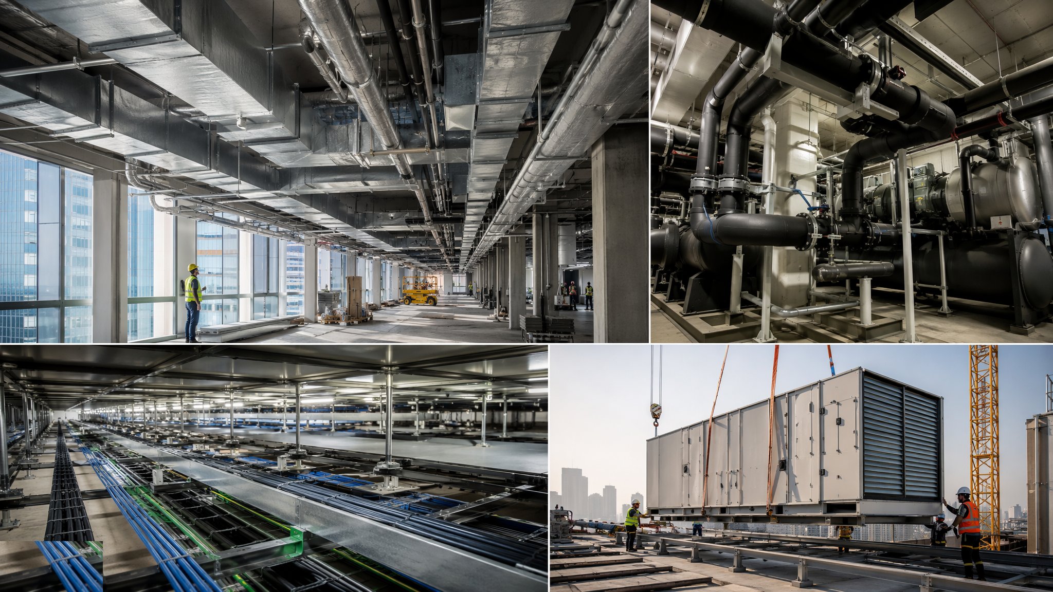
What is VRF/VRV direct expansion?
A variable refrigerant flow system distributes refrigerant rather than water or air. An outdoor condensing unit sits on the roof or in a plant area, refrigerant pipework runs down to the floors, and indoor units in the ceiling, on the wall or in a cassette exchange heat directly with the room air. There is no chilled water circuit, no boiler circuit and no large duct network beyond short local connections. Heat recovery arrangements can move heat from a zone that is cooling to a zone that is calling for warmth. Fresh air is still needed and is usually provided separately by a small ventilation system, because a refrigerant system on its own conditions air that is already in the room.
The reason the system appears so often on refurbishments and on smaller commercial floors is speed and space. Refrigerant pipework is small, so risers can be modest and the ceiling void does not have to accommodate water mains or large ducts. Installation is quick and the system can be built floor by floor and brought into use in stages, which suits phased works and occupied buildings. It also avoids putting a large volume of water above finished ceilings, which some landlords and some occupiers care about a great deal.
The obligations that come with it are different in kind rather than smaller. Refrigerant pipework is a pressure system carrying a fluid that must be contained, and every part of the work on it is work for qualified refrigeration specialists holding the relevant competence, not for general mechanical labour. Jointing, evacuation, charging and any subsequent intervention all sit with those specialists. Where refrigerant enters occupied rooms, the designer will assess the arrangement and decide what containment, ventilation and leak detection the installation needs. The site team does not set those requirements and does not decide them by rule of thumb. Commissioning is also specialist and system specific, and the outcome depends on pipe runs, level differences and joint quality that were fixed weeks earlier by the installation. Condensate still exists at every indoor unit and still has to fall to a drain.
How does VRF/VRV direct expansion work, step by step?
- 1
Step 1: Agree the system layout with the designer and the specialist
The number of outdoor units, the way indoor units are grouped onto them, the pipe routes and the vertical separation between outdoor and indoor units are all interdependent, and they are settled between the services engineer and the specialist installer before anything is ordered. The route length and the height difference between units are constrained, and the constraints belong to the particular system being used, so route options are checked against them early rather than after the risers are formed.
- 2
Step 2: Establish the outdoor unit position and its supports
Outdoor units need airflow around them, structural support beneath them, an acoustic assessment towards the neighbours and a route for replacement in ten or fifteen years. Steelwork or plinths are designed for the load with anti-vibration mounts, and clearances around and above the unit are protected from later additions such as guardrails, screens and other plant. A unit boxed in by things installed after it will not do what the designer assumed.
- 3
Step 3: Install refrigerant pipework as specialist work
Refrigerant lines are installed by the qualified refrigeration contractor. Pipework is supported at the specified spacing, insulated on the runs the designer identifies, protected where it passes through construction, and jointed by the method the specialist uses under an inert gas purge to keep the inside of the pipe clean. Contaminated or badly jointed pipework causes failures that only show up months into operation, which is why this is not work to be shared out among trades on programme pressure.
- 4
Step 4: Coordinate the containment, ventilation and detection the designer specifies
Where refrigerant is distributed into occupied rooms, the designer assesses the arrangement and specifies what is needed: how pipework is contained, how spaces are ventilated and whether leak detection and alarms are required and where. The contractor installs what has been specified and does not substitute a judgement of its own. Detection devices, their wiring and their alarm routing are installed and proved with the rest of the safety systems, and the positions come from the design, not from convenience.
- 5
Step 5: Set the indoor units and their condensate
Indoor units are hung level on anti-vibration fixings with access for filter cleaning and for coil and fan replacement designed into the ceiling. Each unit produces condensate, so the tray fall and the drain run are set out and water tested exactly as they would be for any cooling unit above a finished ceiling. Pumped condensate is used only where a gravity fall genuinely cannot be achieved. Grilles, cassettes and returns are coordinated with lighting and with the ceiling grid.
- 6
Step 6: Pressure test, evacuate and charge under specialist control
The completed pipework is pressure tested, then evacuated to remove air and moisture, then charged. All of this is carried out by the qualified refrigeration specialists, with records kept of the system and its charge. The amount charged, the tolerances and the acceptance criteria belong to that specialist and to the system in question. Nobody else on site adjusts, tops up or vents any part of a refrigerant system.
- 7
Step 7: Commission the system and the controls together
The specialist commissions the system: outdoor and indoor units proved, the addressing of units against zones checked one by one, heat recovery operation demonstrated where it is provided, and any leak detection proved to alarm and to do whatever the design says it should do. The separate fresh air system is commissioned and balanced alongside. Handover includes the system records, the maintenance obligations and a clear statement to the occupier that intervention on the refrigerant circuit is specialist work.
What are the benefits of VRF/VRV direct expansion?
- No water circuits on the floor, so no large wet distribution above finished ceilings
- Small pipework, modest risers and a shallow ceiling void requirement, which suits constrained refurbishments
- Quick to install and can be brought into use floor by floor in phased or occupied buildings
- Heat recovery arrangements can move heat between zones that are cooling and zones that are heating
- Individual room control with a wide range of indoor unit styles to suit different ceilings
- Central plant room requirement is small, freeing lettable area in the building
What are the limitations of VRF/VRV direct expansion?
- All pipework, charging and later intervention is specialist refrigeration work with its own competence requirements
- Fresh air must be provided by a separate system, which still needs riser space and coordination
- Where refrigerant enters occupied rooms the designer may require containment, ventilation or leak detection, and this must be designed in early
- Condensate is still generated at every indoor unit, with the same damage risk as any cooling unit above a ceiling
- Outdoor units need space, structural support, acoustic assessment and a replacement route
- Route lengths and height differences between units are constrained, which limits how far a system can be stretched
What is VRF/VRV direct expansion best suited for?
What plant does VRF/VRV direct expansion need?
- Outdoor condensing units with anti-vibration mounts, steelwork or plinths and lifting arrangements
- Refrigeration specialist tooling for pipe jointing under inert gas purge, plus supports and insulation
- Pressure testing, evacuation and charging equipment operated by the qualified specialist
- Indoor units, cassettes and grilles with their hanging and access provisions
- Condensate pipework, traps and pumps where gravity fall cannot be achieved
- Leak detection devices, alarm wiring and controls equipment where the design requires them
How is VRF/VRV direct expansion quality-checked?
- Route lengths and level differences checked against the system constraints before installation starts
- Refrigeration work carried out and signed by qualified specialists, with competence records held on file
- Pipework jointing witnessed, with purge and cleanliness measures recorded
- Pressure test, evacuation and charging records completed and retained for the system
- Every indoor unit condensate tray and drain water tested before the ceiling closes
- Leak detection and alarm arrangements installed to the design and proved to operate at handover