VAV with central AHUs
One central air plant, big risers, and a box on every branch that varies how much air each zone gets.
Last updated 2026-09-05
What is VAV with central AHUs?
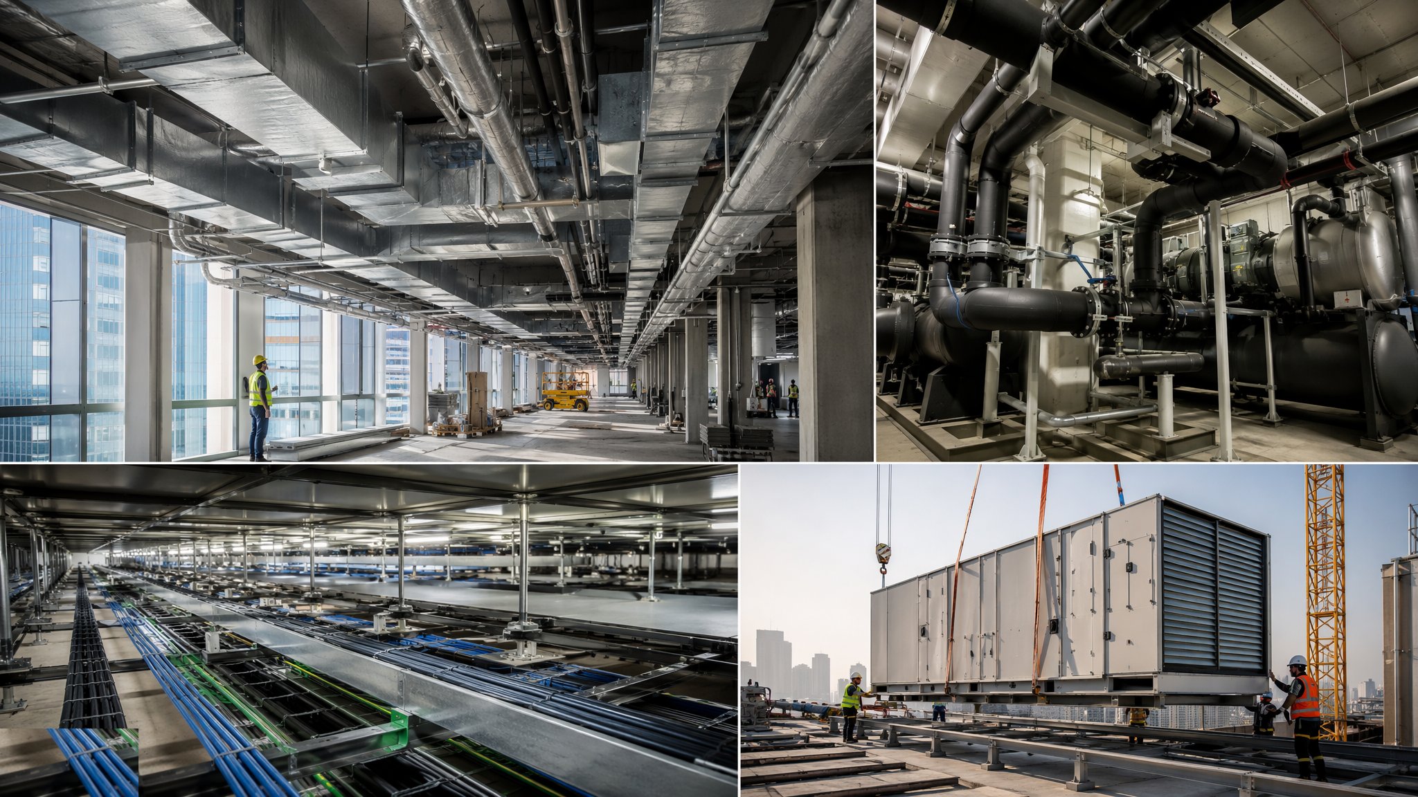
A variable air volume system does the conditioning centrally and then distributes it as air. Central air handling units in a plant room filter, heat, cool and move the air, and it travels down large ducts in the risers and out across the floor. At each zone a terminal box throttles the supply, opening as the zone calls for more and closing back as it satisfies. Some boxes carry a small reheat coil so a zone that has been driven to minimum air can be brought back up in temperature without the whole system changing. The plant is in one place, the machinery on the floor is limited to the boxes and their dampers, and the ceiling void carries ductwork rather than water.
Because everything happens centrally, the plant can be large, efficient and properly maintained by people who only have to visit one room. Filtration is at the plant, so the quality of the air delivered is easier to control and to prove. The system also handles the ventilation and the room load in the same air stream, so there is no separate fresh air system to coordinate. Deep floor plates suit it, because a central core with large risers can push air a long way and internal zones with steady loads are exactly what a big central plant does well. Where the arrangement gets hard is at the edges of the plan, where the load swings with the sun and the weather and a zone can need a much wider range than the box next to it.
The costs of the approach are space and balancing. Moving heat in air needs far more cross-sectional area than moving it in water, so the risers are larger, the plant room is larger and the horizontal ducts are deeper. On a refurbishment where the risers are already built, that alone can rule the system out. And once installed, a VAV system only performs if it is balanced, because the design assumes a particular pressure profile across a network of boxes that are constantly changing. Balancing a full floor of boxes is a serious commissioning exercise with a real duration in the programme, and it is the item most often compressed and most often regretted. The services engineer sets the arrangement, the zoning and the plant for the particular building.
How does VAV with central AHUs work, step by step?
- 1
Step 1: Fix the zoning and the plant strategy early
The designer divides the floor into zones that behave alike, typically separating perimeter from core and separating each facade orientation, and decides how many air handling units serve what. That decision sizes the plant room and the risers, and both are structural commitments made long before the fit-out. On most projects the shell and core design has already fixed them, so a later change of system on the floors is limited by what the risers will physically carry.
- 2
Step 2: Build the plant room and set the air handling units
Units arrive in sections, are craned or skated into a plant room that has to have been built with a route in and a route out for future replacement, and are assembled, sealed and mounted on anti-vibration bases. Access doors, filter withdrawal space and coil removal space are checked against the room as built rather than the drawing. Drainage, power and controls connections are made. A unit that cannot be maintained is a unit that will be run until it fails.
- 3
Step 3: Install the risers and main duct distribution
Large rectangular or circular ducts are assembled, supported and sealed up the riser and out along the floor. Joints are made to the sealing standard the specification calls for, supports are at the spacing specified, and fire dampers are installed at the compartment lines exactly where the fire strategy shows them, with their access panels genuinely reachable. Duct leakage is cumulative and invisible, which is why it is tested rather than judged.
- 4
Step 4: Set the terminal boxes and branch work
Each box is hung level, with the straight length of duct upstream that its damper and sensor need to read the flow correctly. Fitting a box tight against a bend is one of the most common causes of a system that will not balance. Reheat coils, where used, are connected and their pipework run and insulated. Boxes are labelled and their control cabling brought back to the panel, and the label, the zone and the drawing are made to agree at the time of installation rather than at commissioning.
- 5
Step 5: Run the low level distribution and the diffusers
Flexible connections are kept short and straight to the diffusers, because a crushed or coiled flexible is a permanent restriction that no amount of balancing will recover. Diffuser positions are coordinated with the lighting, the sprinklers and any future partition positions the landlord wants to keep open. Where the ceiling is open and the ductwork is exposed, the setting out becomes a finish and is treated as one.
- 6
Step 6: Leakage test and clean the system
Ductwork is leakage tested in sections to the class the specification requires, before insulation and before the ceiling closes. Sections are kept capped and clean during construction, because dust and debris drawn into an open duct end up at the diffusers on the first day of running. Internal cleanliness is inspected and recorded before the system is put into service.
- 7
Step 7: Balance, commission and hand over the settings
The system is balanced from the plant outwards: fan performance proved, main branches set, then every box set to its minimum and maximum flow and each diffuser measured. Controls are commissioned so that each box responds to the sensor in the zone it actually serves, the reheat sequence does not fight the cooling, and the plant resets its pressure as the boxes close rather than throttling against them. Allow proper time for this. A VAV floor that is not balanced looks finished, runs, and never performs.
What are the benefits of VAV with central AHUs?
- Central plant in one place, easier to maintain, monitor and replace than distributed units
- Filtration and air quality handled centrally and provable at a single point
- Ventilation and room conditioning delivered in the same air stream, with no separate fresh air system on the floor
- Very well suited to deep floor plates with large, steady internal zones
- Little machinery above the ceiling on the floor itself, so fewer access panels than a distributed system
- Turndown at the boxes means the plant works less hard when the floor is lightly occupied
What are the limitations of VAV with central AHUs?
- Needs large risers and a large plant room, which are fixed by the base build and hard to change later
- Deep horizontal ducts eat ceiling void and drive floor to floor height
- Balancing is a substantial and unavoidable commissioning exercise that is often squeezed
- Zones on the same air handling unit share a plant condition, so a zone that behaves very differently is awkward
- Duct leakage and crushed flexible connections quietly destroy performance and are hard to find afterwards
- Alterations to the floor layout usually mean altering ductwork, which is more disruptive than moving a water branch
What is VAV with central AHUs best suited for?
What plant does VAV with central AHUs need?
- Sectional air handling units with anti-vibration bases, and the lifting and skating gear to place them
- Duct fabrication, assembly and sealing equipment for risers and horizontal runs
- Terminal boxes with dampers, actuators, sensors and, where used, reheat coils and their pipework
- Fire dampers with their access provisions, installed to the fire strategy
- Duct leakage testing rig and internal cleanliness inspection equipment
- Air flow measuring instruments and balancing gear for plant, branches, boxes and diffusers
How is VAV with central AHUs quality-checked?
- Riser and plant room space checked against the installed units, including withdrawal and replacement routes
- Duct leakage tests carried out section by section before insulation, with certificates issued
- Straight duct lengths upstream of every box verified before the ceiling closes
- Fire dampers logged, positioned to the fire strategy and proved accessible through their panels
- Internal duct cleanliness inspected and recorded before the system is run
- Full balancing record for plant, branches, box minimum and maximum flows and diffusers, with controls proved zone by zone