Free-standing rapid and ultra-rapid units
The familiar forecourt pillar with everything inside it - simple to install, heavy on cable and heavy on the base.
Last updated 2026-09-06
What is Free-standing rapid and ultra-rapid units?
A free-standing rapid or ultra-rapid unit is the charger most drivers picture: a floor-mounted pillar or cabinet standing at the head of a bay, with the cables and connectors hanging from it and a screen on the front. Everything the unit needs to work sits inside that one enclosure. The incoming supply arrives as alternating current, the conversion equipment inside turns it into the direct current the vehicle battery actually takes, and the cooling, metering, payment terminal and communications hardware all share the same housing. Rapid units on most projects sit in the order of 50 kW to 150 kW. Ultra-rapid units commonly deliver in the order of 150 kW and above, with the largest single units now well beyond that. The distinction matters less to the installer than the consequence of it, which is that the higher the output the larger the enclosure, the heavier the unit, the more heat it rejects and the more substantial everything under it has to be.
The attraction of the arrangement is that it is self-contained. One unit, one base, one supply cable, one commissioning exercise, one thing to maintain and one thing to replace. There is no separate plant room to find space for and no distribution running around the site between a cabinet and the bays. On a small project - two or four bays added to an existing car park - that simplicity usually decides it, because the cost and disruption of a distributed arrangement cannot be recovered across so few bays. It is also the arrangement most operators and maintainers know best, which counts for something over a fifteen-year operating life.
The cost of that simplicity shows up in three places. The first is cable. Every unit needs its own supply run back to the point of distribution, and on a large forecourt those runs add up into a substantial quantity of trenching, ducting and cable that a shared arrangement would avoid. The second is the base. These are heavy units, commonly several hundred kilograms and sometimes more than a tonne, standing outdoors in the weather and in the path of vehicles, so the foundation and its ducting are a proper civils operation and not an afterthought. The third is space. A free-standing unit occupies ground at the head of a bay that could otherwise be circulation, landscaping or another bay, and on a constrained site that is often the argument that pushes the designer towards a cabinet-and-dispenser layout instead.
How does Free-standing rapid and ultra-rapid units work, step by step?
- 1
Step 1: Fix the bay layout and the unit positions
The designer sets out where the units stand before anything else is decided, because the position of the pillar drives the base, the ducting, the protection, the lighting, the signage and the swept paths around it. Bay layout has to work for the vehicles the site expects, including the longer cables and wider swings that come with towing and with commercial vehicles. Accessible bays, the routes to and from them and the surfaces around them are set by the designer against the standards for the project, and they are laid out at this stage rather than adjusted later. The number of bays that can be served at all is capped by the supply capacity available, so the layout and the supply strategy are settled together.
- 2
Step 2: Survey the existing site and its services
Most of these projects are on land that is already in use, so the survey matters as much as the design. Existing services are traced and proved, existing drainage is picked up, existing levels are recorded and existing surfacing is assessed for whether it will take excavation and reinstatement neatly. Any part of the site that stays operational during the works is identified now, because that is what dictates the phasing. Unknown buried services are the single most common cause of lost days on a live forecourt.
- 3
Step 3: Excavate, duct and construct the bases
The base is designed for the weight of the unit, for the ground conditions found on site and for the loading it will see from vehicles and from any protection around it. Reinforcement, fixings and ducting are cast in to the designer's details, with the duct entries set out to match the unit's own entry positions - getting that wrong is expensive to correct once concrete has gone off. Ducts are laid, proven clear and left drawn with a rope. The base is given time to gain strength before anything heavy is set on it, and that curing period is a real item on the programme rather than something to be compressed.
- 4
Step 4: Install the containment and pull in the supply cables
Trenches are excavated, ducts and draw pits installed, and the supply cables pulled in from the point of distribution to each base. Route, depth, separation, marker tape and reinstatement all follow the specification and the requirements of whoever owns the ground above. Cable pulling on long runs needs planning - lubrication, roller layout, tension monitoring and enough people - because a cable damaged during the pull may not show itself until testing, or worse, until later in service. Reinstatement is carried out to the standard the site or the highway authority requires, and it is usually the part a client sees first.
- 5
Step 5: Set the units and terminate
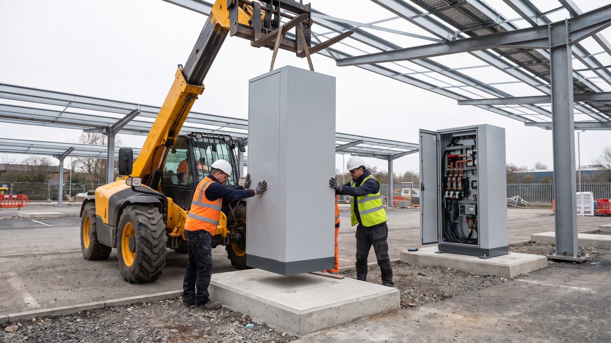
Units are lifted onto their bases with an appropriate appliance, which for the heavier ultra-rapid enclosures means a proper lifting plan rather than a pair of shoulders. They are levelled, bolted down to the manufacturer's fixing arrangement and sealed at the base so that water and vermin cannot get in. Terminations, earthing arrangements and protection are the work of competent qualified electrical people, designed by the designer and carried out under the principal contractor's regime. Communications cabling, whether fixed or wireless, is installed and proved at the same visit so that nobody has to open a sealed enclosure again.
- 6
Step 6: Install protection, drainage, lighting and signage
Bollards, kerbs, wheel stops or barriers protect the unit from vehicle impact to the arrangement the designer has specified. Surface levels are set so that water runs away from the unit and away from the bay, and any drainage alteration is completed rather than left to the landscaping package. Lighting to the bays and the routes to them, wayfinding to get drivers to the chargers, and the operational and safety signage on and around the units are all installed as part of the works. These items are treated on many projects as finishing trades to be squeezed at the end, and they are the ones that generate complaints from day one if they are.
- 7
Step 7: Phase the works bay by bay around a live site
Forecourts, retail car parks and depots very rarely close. The works are normally broken into bays or small groups of bays, each with its own hoarding or barrier line, its own pedestrian and vehicle routing and its own reinstatement, so the site keeps trading throughout. That phasing costs money in repeated set-ups and it lengthens the programme, and both should be in the price from the start. Coordination with the site operator over trading hours, deliveries and peak periods is continuous rather than a single conversation at the outset.
- 8
Step 8: Hand the units over for energisation and commissioning
Once the installation is complete the units are presented for the electrical commissioning and energisation stage, which is a separate exercise carried out by competent qualified people under the network operator's and the principal contractor's regimes. The installer's work at this point is to have the records ready: as-installed drawings, cable schedules, duct routes, base details, product documentation, lifting records and the reinstatement record. A tidy handover pack shortens commissioning, and a poor one turns it into an investigation.
What are the benefits of Free-standing rapid and ultra-rapid units?
- Self-contained - one enclosure holds the conversion, metering, payment and communications hardware
- Simplest arrangement to design, install, commission and later replace
- No separate plant space or cabinet compound to find room for on a constrained site
- Well understood by operators and maintainers, which matters across a long operating life
- A single unit can be taken out of service without affecting its neighbours
- Usually the most economic answer where only a small number of bays is being added
What are the limitations of Free-standing rapid and ultra-rapid units?
- Every unit needs its own supply run, so cable, ducting and trenching quantities climb quickly on larger sites
- Heavy enclosures demand a substantial designed base, cast-in ducting and impact protection
- The pillar occupies ground at the head of the bay that a constrained site may not have
- Output is fixed to the unit, so power cannot be shared between bays when demand is uneven
- Fans and cooling on the higher-output units generate noise close to the bay and to any neighbours
- Larger units are visually prominent, which can be a planning and townscape issue on sensitive sites
What is Free-standing rapid and ultra-rapid units best suited for?
What plant does Free-standing rapid and ultra-rapid units need?
- Excavator and breaker for base excavation and for trenching through existing surfacing
- Mobile crane or lorry loader with a lifting plan for setting the heavier enclosures
- Concrete supply and vibration equipment for the bases, with formwork and reinforcement
- Cable drum trailers, rollers, winch and tension monitoring for the supply pulls
- Service location equipment, ducting, draw pits and duct rodding gear
- Surfacing and reinstatement plant, barriers, hoarding and traffic management for bay-by-bay phasing
How is Free-standing rapid and ultra-rapid units quality-checked?
- Setting out of bases and duct entries checked against the manufacturer's arrangement before concrete is placed
- Base concrete records, reinforcement inspection and a strength check before units are set
- Duct routes proven clear and recorded, with draw ropes left in and pits accessible
- Cable pull records - route, tension and any incidents - kept for every run
- Unit fixing, levelling and base sealing inspected, with lifting records retained
- As-installed drawings, product documentation and reinstatement records assembled before the units are presented for commissioning
More charger installation methods
Next method
Power cabinet with satellite dispensers