Repeat-unit arrangements built for later expansion
The first phase is built so identical units can be added later without shutting the plant down - which constrains layout, spare capacity and access from day one.
Last updated 2026-09-07
What is Repeat-unit arrangements built for later expansion?
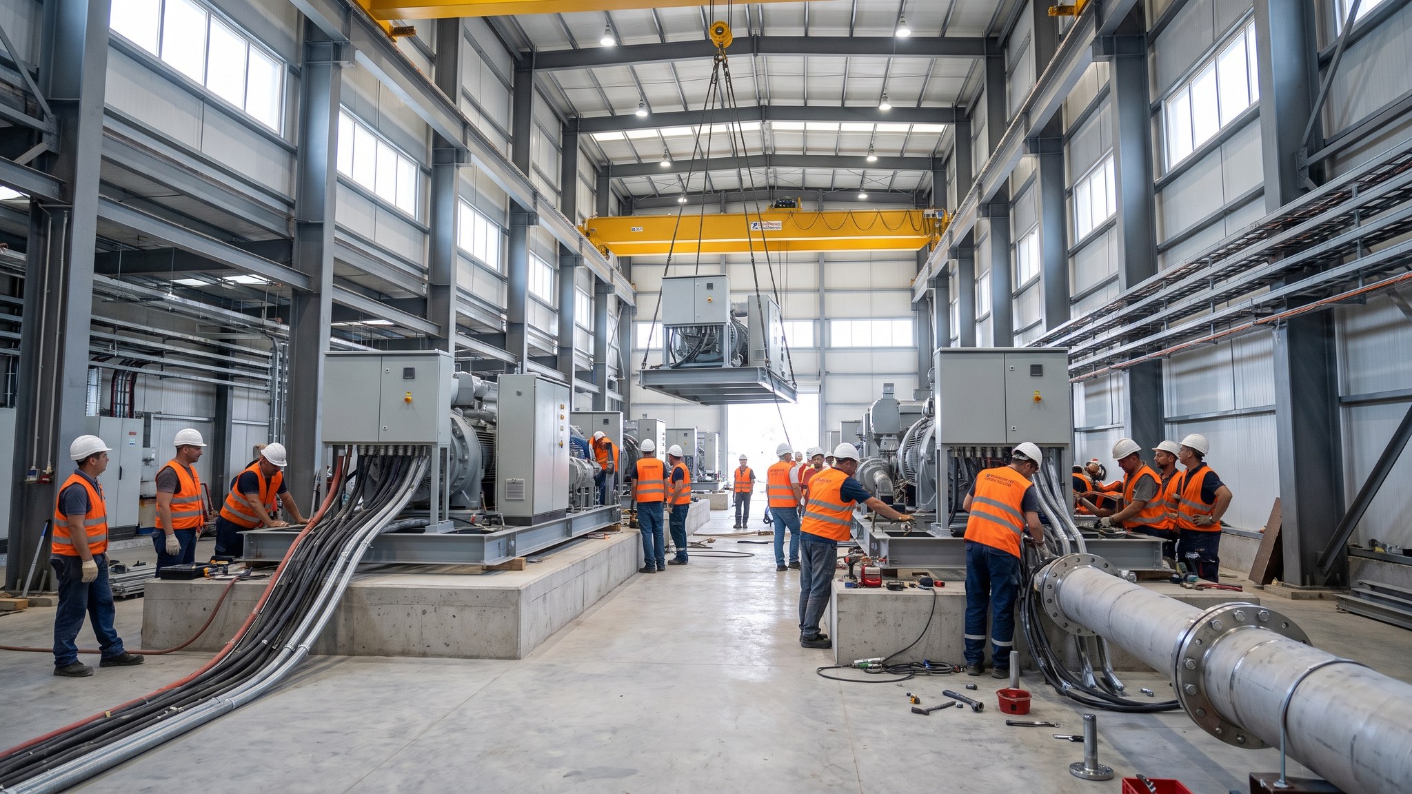
Most hydrogen projects are conceived as the first phase of something larger. Demand is expected to grow, the offtake contracts extend, and the developer wants the option to add capacity without rebuilding. That intention has to be designed in at the start, because retro-fitting expandability into a completed process plant is close to impossible. The arrangement is a repeat unit: a defined block of plant - electrolysis modules, their electrical supply, their water treatment and their gas handling - that can be replicated on a prepared position.
Designing for repeat units changes decisions across the whole project. The layout has to leave the expansion positions free and, crucially, has to leave the access to reach them - a crane cannot land a module on a position it cannot reach past the plant already operating. Utilities are sized either for the ultimate capacity or with a defined path to being upgraded. The electrical infrastructure needs spare capacity or space for additional transformers and switchgear. Buried service corridors are laid with spare ducts and capped connections. Drainage is sized or arranged for extension. The first phase therefore costs more than a standalone plant of the same size, and the difference is the price of the option.
The hardest requirement is that the expansion must happen without shutting the operating plant down. Once the first phase is producing hydrogen, later construction is taking place next to a live process handling a gas that forms an explosive atmosphere over a very wide range and burns with an almost invisible flame. That is why the isolation points, the tie-in arrangements and the physical separation between the operating plant and any future construction area are all designed at the outset, by the designer with the technology supplier and the regulator. It is also why the construction team building phase one should be thinking about how phase two will be built - where the fence will run, where the hardstanding will be, which connections will be broken into and how they will be isolated. Those choices are cheap to make on paper in phase one and very expensive to fix later.
How does Repeat-unit arrangements built for later expansion work, step by step?
- 1
Step 1: Define the repeat unit
The project defines exactly what a repeat unit contains - which electrolysis modules, which electrical supply equipment, which water treatment and gas handling, and which civils. Everything inside that block is replicable; everything outside it is either shared infrastructure sized for the ultimate capacity or infrastructure with a defined upgrade path. On most projects this definition is settled with the technology supplier early, because it determines what the shared systems have to cope with.
- 2
Step 2: Master-plan the site for the ultimate capacity
The site is laid out for the final plant, not the first phase. Expansion positions are identified and kept clear, and the separation between operating and future areas is set by the designer, the technology supplier and the regulator on hazard grounds. Land that will be needed later is protected from being used for laydown, offices or car parking that would be awkward to move. On most projects the master plan is a controlled document and any use of a reserved area needs approval.
- 3
Step 3: Protect construction access to the expansion positions
A future module has to be delivered and lifted onto a position that will by then be surrounded by an operating plant. The routes, the crane standing positions and the lifting envelopes for the expansion are worked out during phase one and protected - not built over, not planted, not used for permanent storage. Where the hardstanding will be needed it is often built in phase one, because building it later means working alongside live plant. This is the constraint most often overlooked and the most expensive to recover.
- 4
Step 4: Size shared infrastructure or define its upgrade path
Water treatment, cooling, firewater, compressed air, control systems and drainage are either built for the ultimate capacity or built with a defined, designed route to being upgraded. Building everything to ultimate capacity costs money that sits idle; building only for phase one risks an upgrade that requires a shutdown. On most projects the decision is taken system by system on cost against the risk of interrupting production, and it is recorded so that phase two knows what it inherited.
- 5
Step 5: Build electrical capacity and space for expansion
The electrical compound is laid out with space for the additional transformers, rectifiers and switchgear that later units will need, and the incoming connection is arranged to allow the additional load. Spare ways in ducts, spare cable routes and spare positions on switchboards are provided. This is the most expensive element of designing for expansion and the one that most clearly separates a plant that can grow from one that will need rebuilding to grow.
- 6
Step 6: Install spare ducts, tie-in points and isolation from the outset
Buried service corridors are laid with spare ducts and capped, recorded connection points at the positions where the expansion will tie in. Isolation arrangements are designed and installed so that a future tie-in can be made with the operating plant isolated from the work. Those isolation points are specified by the designer and the technology supplier, and their positions are recorded in the as-built documentation so that phase two can find them.
- 7
Step 7: Build a first unit that is genuinely repeatable
The first unit is built and documented as a template. Foundation details, bolt geometry, connection arrangements, cable routes, test procedures and the as-built survey all become the basis for the next unit, so the second is quicker and cheaper. On most projects the lessons from phase one are formally captured for phase two rather than lost with the site team, and small standardisations made in phase one repay themselves several times over.
- 8
Step 8: Plan phase two construction alongside a live plant
When the expansion is built, it is built next to an operating plant handling hydrogen. The construction area is physically separated from the operating plant, the permit system governs any work near live systems, and the tie-ins are made at the designed isolation points under procedures agreed with the operator, the technology supplier and the regulator. On most projects the operator retains control of the site throughout, and the construction contractor works under the operating plant's rules rather than its own.
What are the benefits of Repeat-unit arrangements built for later expansion?
- Capacity can be added without redesigning or rebuilding the plant
- The second and later units are quicker and cheaper because the first is a documented template
- Shared infrastructure sized once serves several units, improving overall cost per unit of capacity
- Expansion can be built without shutting down production, protecting revenue and offtake commitments
- Matches the way demand for hydrogen actually develops - incrementally and with uncertainty
- Spare ducts, tie-in points and isolation designed in from the start avoid excavation near live plant later
What are the limitations of Repeat-unit arrangements built for later expansion?
- The first phase costs more than a standalone plant of the same size - that difference is the price of the option
- Reserved land and protected access routes constrain the phase one layout and cannot be used for anything else
- Shared infrastructure sized for ultimate capacity sits underused for years
- The expansion may never happen, in which case the additional cost delivers nothing
- Building alongside an operating hydrogen plant is a demanding and heavily controlled construction environment
- Technology moves on, so later units may not be identical to the first and the template may need revision
What is Repeat-unit arrangements built for later expansion best suited for?
What plant does Repeat-unit arrangements built for later expansion need?
- The same lifting, transport and installation plant as the base installation method, planned for repeat use
- Cranes able to reach protected expansion positions past the operating plant
- Civils plant for foundations and hardstanding at expansion positions, often built during phase one
- Duct laying and cable installation equipment for spare ways and capped tie-in points
- Survey equipment to replicate the template geometry accurately on each new unit
- Isolation, testing and permit-controlled tie-in equipment for work adjacent to live plant
How is Repeat-unit arrangements built for later expansion quality-checked?
- Master plan for the ultimate capacity issued as a controlled document, with reserved areas protected
- Construction access, crane positions and lifting envelopes for future units recorded and preserved
- Spare duct ways, capped connections and isolation points recorded accurately in the as-built documentation
- Shared system capacity and upgrade paths documented system by system for the next phase
- First unit fully documented as a template - foundation details, bolt geometry, connections and test records
- Tie-in procedures agreed with the operator, the technology supplier and the regulator before any work near live plant