Loading and offtake facility pipework
The interface where the plant meets a trailer, a ship or a customer connection - the busiest and most operated part of the whole installation.
Last updated 2026-09-07
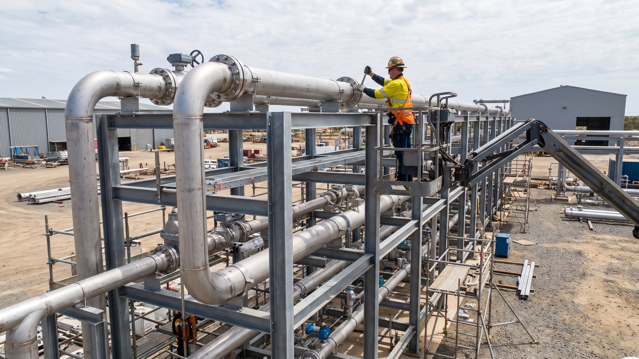
What is Loading and offtake facility pipework?
A production plant only earns anything when the hydrogen leaves it, and the point at which it leaves is the loading and offtake facility. It might be a road loading bay where trailers are filled, a jetty arrangement where a vessel is loaded, or a connection point where a pipeline hands over to a customer or a network. Whatever the form, this is the part of the plant with a characteristic the rest does not share: it is operated constantly. Elsewhere the pipework is made once, proved once and then left alone under monitoring. Here, connections are made and broken every working day, by people, often by people who do not work for the plant.
That changes what the design has to achieve. The engineering discipline is the same - materials selected by the designer for hydrogen service, joint integrity governing everything - but it is applied to an arrangement that is coupled and uncoupled routinely rather than joined permanently. The designer provides a connection arrangement built for repeated use, isolation that lets the connection be made and released safely, and protection against the things that go wrong at an interface: a vehicle moving while connected, a connection released under the wrong conditions, a coupling damaged by handling. Vehicle movement, stand positions, approach and departure routes and the position of everything relative to occupied buildings and the boundary all come from the hazard assessment.
The commercial and operational interface is as important as the physical one. The facility is where the plant's responsibility ends and someone else's begins, so metering, quality measurement, documentation and the point of custody transfer are all defined and built into the arrangement. Drivers and vessel crews are people from outside the plant who need to be inducted, controlled and given clear procedures. On most projects the loading facility is also the part of the plant the operator most wants to expand later, because throughput is what the business depends on, so a sensible design leaves room and connection capacity for additional positions from the outset.
How does Loading and offtake facility pipework work, step by step?
- 1
Step 1: Establish the offtake arrangement the plant is being built for
The operator and the designer settle how the hydrogen leaves: by road, by water, by pipeline to a customer, or by more than one route. That decision drives everything about the facility, from the civils to the control system to the number of people on site each day. On most projects the offtake arrangement is fixed by a commercial contract before the plant is designed, and the facility is built to serve that contract rather than to serve every possibility.
- 2
Step 2: Take the layout and the vehicle arrangement from the hazard assessment
The hazard assessment agreed between the designer, the technology supplier and the regulator sets where loading positions sit, how they are separated from each other and from the rest of the plant, and how vehicles or vessels approach, stand and leave. Movement in and around a live loading operation is part of that assessment. The civils package builds the arrangement as designed - hardstanding, stands, marking, protection and access - rather than laying it out for traffic convenience.
- 3
Step 3: Design the connection arrangement for repeated use
The connection at a loading position is not a permanent joint. It is a designed arrangement made for coupling and uncoupling by an operator many times over, with the isolation, protection and support the designer specifies. Wear, handling damage and the consequences of a connection being released at the wrong moment are all designed for. The technology supplier and the designer settle the arrangement together, and the operator's procedures are written around it.
- 4
Step 4: Build the civils, stands and protection
Hardstanding designed for loaded vehicle weights, stand and parking positions, turning and manoeuvring areas, drainage, marking and physical protection for equipment against vehicle impact are all built as part of the facility. Where the offtake is marine, the works extend onto the jetty structure and coordinate with the marine operator. Protection against impact deserves particular attention, because vehicle contact with pipework or a connection point is one of the more likely incidents at a facility of this kind.
- 5
Step 5: Install the process pipework, isolation and metering
The pipework serving the facility is installed to the same regime as the rest of the plant: materials specified for hydrogen service, traceability maintained, joints made by qualified specialists and recorded individually. Isolation arrangements, emergency shutdown devices, metering and any quality measurement required for custody transfer are installed to the design. Metering matters commercially as well as technically, because it is the basis on which the plant is paid.
- 6
Step 6: Install detection, shutdown and emergency provision
Gas and flame detection, emergency shutdown devices reachable from where people actually stand, firewater provision, earthing arrangements for vehicles and the means to stop a loading operation immediately are installed to the safety design. Because the facility is operated by people at close quarters, the position and accessibility of shutdown devices is a design decision made deliberately rather than an afterthought at installation.
- 7
Step 7: Write the operating, access and third-party procedures
The facility needs procedures covering how a vehicle or vessel arrives, is checked, is positioned, is connected, is loaded, is disconnected and departs, who is authorised at each step, how third-party drivers and crews are inducted and controlled, and what happens when anything is abnormal. These are written for that facility with the technology supplier's input and form part of the operator's permit system. Training and authorisation are completed before the first loading operation.
- 8
Step 8: Prove the facility and run trial operations
Purging, inerting, leak testing and first fill are the most hazardous activities on the whole project, carried out by specialists under the operator's permit system to procedures written for that plant, and nothing about them is generic. Once the facility is proved, most operators run trial loading operations with the technology supplier and the offtaker present, so that the procedures, the metering, the documentation and the people are all tested together before commercial operation begins.
What are the benefits of Loading and offtake facility pipework?
- Provides the interface on which the plant's commercial output depends
- Connection arrangements designed for repeated use rather than as permanent joints
- Metering and quality measurement at the point of custody transfer support the commercial contract
- Concentrates third-party access into one controlled area rather than across the plant
- Can be laid out to allow additional loading positions as throughput grows
- Emergency shutdown provision is placed where the people operating the facility actually stand
What are the limitations of Loading and offtake facility pipework?
- The most operated part of the plant, with connections made and broken every working day
- Third-party drivers and crews are people the operator does not employ but must control
- Vehicle movement close to live equipment brings an impact risk that has to be designed against
- Wear and handling damage to connection arrangements create an ongoing maintenance obligation
- Throughput is limited by the number of positions, so expansion means further construction
- Marine offtake adds a further operator, a further set of interfaces and tidal working constraints
What is Loading and offtake facility pipework best suited for?
What plant does Loading and offtake facility pipework need?
- Paving and concreting plant for hardstanding, stands and manoeuvring areas
- Pipe fabrication, jointing and inspection equipment operated by qualified specialists
- Cranes and handling equipment for loading arms, connection arrangements and canopies
- Survey instruments for setting out loading positions and connection points
- Metering, instrumentation and calibration equipment for custody transfer arrangements
- Detection, earthing and shutdown installation and test equipment
How is Loading and offtake facility pipework quality-checked?
- Materials specified for hydrogen service and traced from order to installed position
- Every made joint recorded in a joint register with operative, procedure and inspection
- Metering and quality measurement calibrated and certified before commercial operation
- Emergency shutdown devices proved from every position at which an operator works
- Connection arrangements demonstrated through repeated coupling and uncoupling before service
- Trial loading operations completed and recorded with the operator and the offtaker present