Vent, relief and utility headers
The systems that take gas safely away from plant when something goes wrong - designed entirely by the designer, and never adjusted on site.
Last updated 2026-09-07
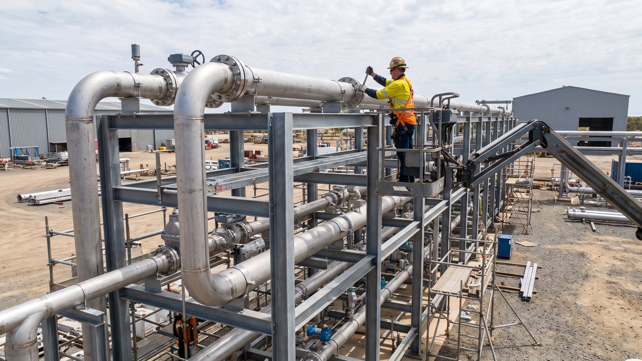
What is Vent, relief and utility headers?
Every hydrogen plant has a set of systems whose only purpose is to deal with the abnormal. When a device operates to protect equipment, when a system has to be emptied for maintenance, when a machine trips or when the plant shuts down, the gas has to go somewhere, and the vent and relief systems are where it goes. Alongside them run the utility headers the plant depends on: nitrogen for purging and inerting, instrument air, cooling water, and the drains. These systems attract less attention than the process pipework because they are not what the plant is for. They are, however, the systems that determine what happens on the worst day, and they are treated accordingly.
Everything about them is settled by the designer. Where relief devices are placed, what they protect, where their discharge is routed, how the collecting headers are arranged, where a vent terminates and how the discharge behaves when it leaves - all of that comes out of the process safety design carried out by the designer with the technology supplier and agreed with the regulator. It is not adjustable on site, and it is not a place for practical improvisation. A vent route altered to clear an obstruction, a header re-graded to suit a support, or a discharge point moved to avoid a clash can change how the system behaves when it operates. Where a site constraint makes the design impossible to build as drawn, the answer is a technical query back to the designer, every time.
What the contractor brings is disciplined installation. The same material compatibility and joint integrity rules apply as on the process pipework - these lines carry hydrogen too, and a leaking vent header is no less serious than a leaking process line. Headers are usually arranged so that they drain in the direction the design intends and stay free of anything that could collect and obstruct them, which makes falls, supports and the avoidance of unintended low points matters of substance rather than workmanship preference. The nitrogen system deserves separate mention: it is the means by which the plant is purged and inerted, so it has to be complete, proved and available before the most hazardous activities of the whole project can begin, and its own hazard - an atmosphere in which people cannot breathe - is managed under the operator's permit system.
How does Vent, relief and utility headers work, step by step?
- 1
Step 1: Take the whole arrangement from the process safety design
Relief device positions, what each protects, where discharges are collected, how headers run and where vents terminate are all outputs of the process safety design produced by the designer with the technology supplier and agreed with the regulator. The contractor receives that as a fixed arrangement. Nothing in it is optimised, rerouted or re-positioned on site, and any constraint that makes it unbuildable as drawn goes back as a technical query.
- 2
Step 2: Install the relief devices as specified and set
Relief devices arrive with settings established by the designer and certified by the supplier, and they are installed in the specified position and orientation without alteration. Isolation arrangements around them are installed exactly as designed, because a device isolated when it should not be is a defeated protection. Certification and settings records are held for each device and passed to the operator, who will maintain and re-certify them for the life of the plant.
- 3
Step 3: Build the collecting headers to fall and free of low points
Headers are installed so that they drain in the direction the design intends, with the supports arranged so that no unintended low point is created where anything could collect and obstruct the route. Falls are proved by survey rather than judged by eye. Support positions come from the design and are not moved to suit an obstruction, because a header sagging between supports creates exactly the low point the design was arranged to avoid.
- 4
Step 4: Erect the vent structures as designed
Vent structures and their supports are erected in the designed position, to the designed arrangement, with the discharge configured exactly as specified. Their position relative to occupied buildings, walkways, access routes, the boundary and any adjacent structure is a safety decision made by the designer and agreed with the regulator, and it is not adjusted for construction convenience. Access for inspection and maintenance is provided as designed.
- 5
Step 5: Install the nitrogen system and prove it early
The nitrogen system is what makes purging and inerting possible, so it is one of the first systems completed and proved. It is installed to the same jointing and traceability discipline as the process pipework. It carries its own serious hazard, because an inerted space is one in which a person cannot breathe, and every point at which nitrogen can be introduced is identified, labelled and controlled under the operator's permit system before the system is used.
- 6
Step 6: Install instrument air, cooling and drainage headers
Instrument air, cooling water and drainage headers are installed to the design and proved. These systems are undramatic but the plant does not run without them, and control devices that fail on loss of air, or cooling that fails on a compressor, take the plant down as surely as a process fault. Drainage is arranged to the design so that what is drained goes where the design intends and not into the general site system.
- 7
Step 7: Prove the systems with the protection they serve
Vent, relief and utility systems are not proved in isolation. They are demonstrated together with the equipment and the shutdown arrangements they protect, so that the operation of a device routes to the place the design says and the plant responds as intended. Testing is planned by the designer and the technology supplier, carried out under the operator's permit system, and recorded system by system.
- 8
Step 8: Hand over with the records the operator will live on
Handover includes the relief device certificates and settings, the header as-built survey and falls record, the joint register, the material traceability and the maintenance regime the operator inherits. These are the records the operator refers to every time a device is re-certified or a header is modified. The activities that bring hydrogen into the systems for the first time remain the most hazardous on the whole project and are carried out only by specialists under the operator's permit system.
What are the benefits of Vent, relief and utility headers?
- Provides a designed route for gas to leave the plant safely when protection operates
- Collects discharges from across the plant into arrangements the designer has assessed as a whole
- The nitrogen system makes purging and inerting possible and is proved before it is needed
- Utility headers give the plant the air, cooling and drainage that keep it running and safe
- Relief device certification and settings give the operator a clear maintenance baseline
- Systems are proved together with the equipment they protect rather than in isolation
What are the limitations of Vent, relief and utility headers?
- Nothing in the arrangement can be adjusted on site, so clashes always become design queries
- Vent structures are tall, visible and constrain what can be placed near them
- Falls and support positions demand a level of installation discipline above ordinary pipework
- The nitrogen system introduces an asphyxiation hazard that must be controlled by permit
- Relief devices carry a continuing certification and maintenance obligation for the operator
- These systems attract less attention than process pipework yet fail with greater consequence
What is Vent, relief and utility headers best suited for?
What plant does Vent, relief and utility headers need?
- Pipe fabrication and jointing equipment operated by qualified specialists
- Cranes and access equipment for erecting vent structures and elevated headers
- Precise levelling instruments for proving header falls and support settings
- Relief device handling, setting verification and certification equipment
- Nitrogen supply and distribution equipment for purging and inerting operations
- Test and calibration equipment for instrument air, cooling and shutdown proving
How is Vent, relief and utility headers quality-checked?
- Relief device certificates and settings recorded and issued device by device
- Header falls proved by survey and recorded, with low points confirmed absent
- Support positions and settings checked against the design one by one
- Vent structure position and discharge arrangement confirmed against the safety design
- Nitrogen system proved, labelled and brought under permit control before first use
- Protective functions demonstrated end to end with the equipment they serve, and recorded