Bunded electrical compounds and transformer bases
Electrolysis is an enormous electrical load, so the transformer and rectifier compound is a major structure with containment, security and access of its own.
Last updated 2026-09-07
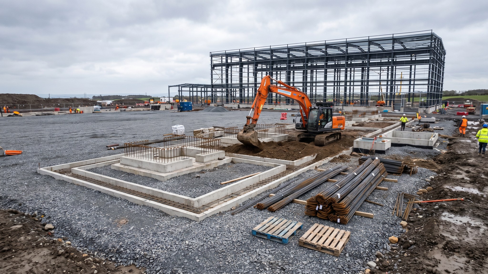
What is Bunded electrical compounds and transformer bases?
The thing that surprises people new to hydrogen projects is how much of the site is electrical. Electrolysis splits water using electricity, and at production scale the demand is comparable with a substantial industrial works or a small town. The current has to be brought in at high voltage, transformed down, converted from alternating to direct current and delivered to the electrolysis packages. That equipment - transformers, rectifiers, switchgear, control and protection - occupies a compound that on many sites is one of the largest single structures on the project, and it is civils-heavy in a way the process areas are not.
Transformers are the reason the compound looks the way it does. They are extremely heavy, they are often oil-filled, and the design has to assume that oil could escape. On most projects each transformer therefore sits on a base within a containment structure sized by the designer to hold the oil inventory together with an allowance for firewater, drained through an interceptor arrangement so that clean rainwater can leave but oil cannot. Around and between the units the designer commonly specifies fire separation - walls, blast-resistant barriers or spacing - and the civils package builds it. The compound also carries the cable route infrastructure: deep multi-way ducts, cable trenches, pits and pull points, and support foundations for the busbar and cable systems running out to the process area.
Access and security are designed in rather than added. Transformers arrive as abnormal loads and may need to be removed and replaced during the plant's life, so a permanent hardstanding access route with adequate turning and lifting positions is provided from the outset. The compound is normally separately fenced with controlled access, both for electrical safety and because it is the most valuable and most vulnerable equipment on the site. The grid connection itself usually drives the programme: the date the connection becomes available is fixed by others and is rarely movable, so the compound civils are commonly the first substantial concrete on the project and are then handed over well before the process areas are complete.
How does Bunded electrical compounds and transformer bases work, step by step?
- 1
Step 1: Take the electrical layout and the connection date as fixed
The compound layout comes from the electrical designer working with the network operator and the technology supplier. Equipment positions, clearances, cable routes and the incoming connection point are settled first. On most projects the date the grid connection becomes live is set by others and cannot be moved, so the civils programme is written backwards from it. That single date normally makes the compound the first major structure on the site and puts it on the critical path from the outset.
- 2
Step 2: Design the containment around the oil inventory
The designer sizes the containment to hold the oil inventory of the equipment it serves plus an allowance for firewater, and specifies how it is drained. Rainwater has to be able to leave the containment without carrying oil with it, which normally means an interceptor arrangement and a controlled outfall. The structure is designed to retain liquid, so joint detailing, waterstops and the finish of the concrete matter more than they would in an ordinary base. The specification, not site preference, sets the details.
- 3
Step 3: Build the bases for very heavy static loads
Transformer and rectifier bases carry concentrated static loads, and the equipment above is intolerant of differential settlement. On the ground these plants occupy the bases are normally piled and tied into the wider foundation framework. Rail plinths, jacking points and anchor positions are cast in to suit the way the supplier intends the unit to be moved into place and, one day, moved out again. Those details come from the equipment drawings and are treated as hold points on the pour.
- 4
Step 4: Install the earthing grid and cable routes first
The earthing installation for a compound of this size is extensive and is installed before the slabs and bases are cast. Conductors, connection points and test facilities are set out to the electrical design, with joints inspected and recorded before anything is covered. Multi-way ducts, cable trenches, draw pits and pull points are built in the same sequence. On most projects this is the stage where the civils contractor is most exposed to electrical design change, so the duct arrangement is confirmed as late as possible and as early as necessary.
- 5
Step 5: Form fire separation and blast-resistant structures
Where the design calls for separation between transformer units, or between the compound and adjacent equipment, the civils package builds it: reinforced walls, barriers or specified spacing. These structures are designed for their duty and the reinforcement, connections and detailing follow the designer's drawings exactly. They are usually built early because they interact with access for the equipment deliveries that follow.
- 6
Step 6: Build the permanent access route and hardstanding
Transformers arrive as abnormal loads and the route from the site entrance to the base is designed as a permanent structure, not a temporary haul road. Turning areas, crane standing positions and lifting hardstanding are all designed for the specific loads, and on most projects they are retained for the life of the plant so that a failed unit can be replaced. Overhead clearances and buried services under the route are checked against the delivery envelope before the route is built.
- 7
Step 7: Complete the security enclosure and controlled access
The compound is fenced separately from the site perimeter with controlled access points, and the foundations for fencing, gates, barriers, lighting columns and any detection equipment are built as part of the package. The arrangement is set by the electrical safety requirements and the security assessment. Gate positions have to suit both routine operator access and the delivery envelope of the largest item, which is a coordination item worth settling on paper.
- 8
Step 8: Test the containment and hand over to the electrical contractor
Before handover the containment is proved: the structure is checked for liquid retention, the drainage and interceptor arrangement is tested, and the falls are confirmed by survey. Earthing continuity and test results are recorded and issued. The compound is then released to the electrical contractor as a documented handover with as-built surveys, duct records and outstanding items attached. On most projects this handover happens months before the process areas are finished, so the compound is fenced and protected while construction continues around it.
What are the benefits of Bunded electrical compounds and transformer bases?
- Contains oil and firewater at source rather than relying on the site drainage system
- Gives the heaviest and least tolerant equipment on the plant a foundation designed for its static loads
- Allows the compound to be completed early and handed over independently to suit the grid connection date
- Builds in permanent access so a transformer can be replaced during the plant's operating life
- Puts the extensive earthing installation in before slabs are cast, where it can be inspected and recorded
- Separates the highest-value and highest-hazard electrical equipment behind its own controlled access
What are the limitations of Bunded electrical compounds and transformer bases?
- A large, expensive and reinforcement-heavy structure that consumes a disproportionate share of the civils budget
- Normally on the critical path from day one because the grid connection date is fixed by others
- Highly sensitive to electrical design change - a duct route revision after the slab is cast is very costly
- Containment structures demand a standard of concrete detailing above ordinary industrial work
- Abnormal-load access routes take up land and constrain the rest of the site layout
- Interceptor and containment drainage adds an ongoing operational maintenance obligation
What is Bunded electrical compounds and transformer bases best suited for?
What plant does Bunded electrical compounds and transformer bases need?
- Piling plant and cranes for the transformer and rectifier bases
- Excavators for containment structures, cable trenches and deep duct runs
- Formwork systems suited to liquid-retaining walls and slabs
- Concrete pumps and vibrators, with batching arranged for continuous pours in retaining structures
- Earthing installation equipment with connection and testing gear
- Rollers and pavers for the permanent abnormal-load access route and hardstanding
How is Bunded electrical compounds and transformer bases quality-checked?
- Containment volume and falls checked against the designer's requirement and proved by survey
- Liquid retention of the containment structure tested before handover
- Interceptor and drainage arrangement tested and recorded
- Earthing conductors and joints inspected and recorded before being covered
- Base levels and cast-in anchor positions surveyed against the equipment supplier's drawings
- Duct routes proved and recorded as built, with draw pits and pull points located on the survey record