Piled foundations with caps, ground beams and plinths
The normal answer on port and industrial land - one piled setting-out framework carrying process, electrical and pipe-rack loads together.
Last updated 2026-09-07
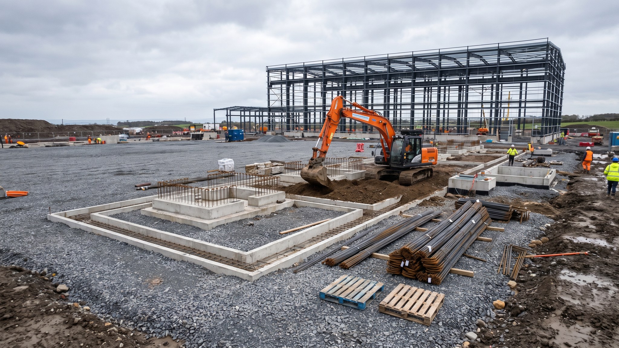
What is Piled foundations with caps, ground beams and plinths?
Hydrogen production plants are built where the power and the offtake are, and that means reclaimed dock estate, former refinery and chemical land, filled quarries and low-lying coastal industrial ground. Almost none of it offers a competent bearing stratum near the surface. On most projects the answer is piling, and the piling is not a single foundation type serving a single structure. One plant carries process skids that will not tolerate differential movement, a transformer and rectifier compound with heavy static loads, pipe racks and cable racks that run across the whole site, gas treatment and compression equipment, storage, a control building and a firewater installation. Each has its own tolerances, and each has to end up in the right place relative to the others because the pipework and cabling between them is fabricated to a model rather than measured on site.
That is why the piled foundation on a hydrogen project is best understood as one setting-out framework rather than a collection of separate bases. The designer sets a single site grid, ties every pile cap, ground beam and plinth to it, and holds the whole plant to tolerances driven by the tightest item on the site. Skid-mounted process packages typically arrive with base frames drilled to a supplier drawing, so the holding-down bolts have to match a factory that has already built the unit. Getting a bolt group wrong is not a snag - it is a package that will not land. The specialist contractor commonly sets bolts in cast-in frames or templates rather than trusting individual positions, and the survey control on these sites is closer to what a structural steel job would use than what a groundworks package normally carries.
The programme logic runs backwards from the technology supplier. On most projects the electrolysis packages and the transformers have long lead times, fixed transport windows and a delivery sequence agreed months ahead, and the civils exist to make sure the correct foundation is complete, cured, surveyed and released on the day each package arrives. That means the foundations are rarely built in a neat geographic sweep. They are built in the order the mechanical and electrical programme needs them, with concrete pours prioritised by delivery date rather than by convenience. It also means hazardous-area thinking is already in play before any concrete is poured. Hydrogen forms an explosive atmosphere across a very wide range and burns with a flame that is almost invisible in daylight, so the designer, the technology supplier and the regulator between them fix which areas of the site are treated as hazardous, and that decision governs where equipment sits, where ignition sources are allowed, where drainage may run and therefore where the foundations go. The civils designer receives that layout as a constraint, not as something to be optimised around.
How does Piled foundations with caps, ground beams and plinths work, step by step?
- 1
Step 1: Take the layout from the hazardous-area decision
The foundation layout is not drawn first. The designer, the technology supplier and the regulator between them settle which parts of the plant are treated as hazardous and how process, electrical and occupied areas are separated from one another, because hydrogen behaves differently from the fuels most industrial sites are used to. Those decisions fix where the electrolysis packages, the electrical compound, the gas treatment, the storage and the control building can sit relative to each other and to the boundary. Only then does foundation design begin. On most projects the civils designer treats that layout as fixed input and raises any clash back through the technology supplier rather than moving equipment to suit the groundworks.
- 2
Step 2: Investigate ground that has an industrial past
The land these plants occupy has usually been used before. Ground investigation on most projects has to find the competent stratum, establish groundwater and any tidal influence, and identify contamination, buried obstructions, old foundations, tanks, culverts and abandoned services left by the previous occupier. Made ground on former industrial land is variable across short distances, so the investigation is closed up wherever the fill changes. The results settle the pile type - driven, bored or continuous flight auger - and they also settle how much of the programme has to be spent removing what is already there. Obstruction clearance ahead of piling is a common and commonly underestimated item.
- 3
Step 3: Fix one site grid and hold everything to it
A single primary control network is established across the whole site and every structure is set out from it. Secondary control is established in each area and checked back to the primary network rather than chained forward from the last structure. The specification sets position and level tolerances for pile caps, for plinth tops and for holding-down bolts, and the tightest of those normally comes from the technology supplier rather than from the civils designer. On most projects the survey record is a live document, updated as each element is completed, because the mechanical contractor will design pipe spools and cable routes off the as-built survey.
- 4
Step 4: Build the working platform and install the piles
Piling rigs are heavy and top-loaded and they stand on the weakest ground on the project. The platform is a designed and certified structure, laid on a proven formation, inspected while the works run and re-certified when rig traffic damages it. Piles are then installed to the designer's depths and set-out, with an installation record kept for every pile. On a contaminated former industrial site the arisings are a waste stream in their own right, segregated, tested and disposed of under the site waste management plan. Integrity and load testing follow the specification and are agreed before the rig arrives rather than negotiated after a poor result.
- 5
Step 5: Cast caps and ground beams as one framework
Caps are cast to the piles, and ground beams tie them into a framework that spreads load and holds the geometry of the plant. Reinforcement is heavy, congested and full of cast-in items, so on most projects the fixing sequence is planned around the items that have to be positioned accurately rather than around the steel. Earthing conductors, service ducts, drainage penetrations and cable-route sleeves are all built in at this stage. Cutting a hole afterwards through a cap on a plant that handles hydrogen is not a small matter, and the designer will normally refuse it.
- 6
Step 6: Set holding-down bolts to the supplier drawing
The bolt groups are the interface between the civils and everything that follows. On most projects they are set in fabricated templates or cast-in frames, surveyed before the pour, surveyed again after it, and protected until the package arrives. The dimensions come from the technology supplier's certified drawings, and any revision to those drawings is treated as a hold point on the pour. Bolt threads are covered and the projection is checked, because a damaged thread found on the day of a lift stops a delivery that may have been scheduled for months.
- 7
Step 7: Form plinths, kerbs and containment to the process design
Plinths raise equipment clear of the surrounding surface, kerbs and upstands direct spillage and washdown where the drainage design wants it, and containment structures are formed where the design calls for them. The falls, the joint positions and the surface finish all matter more here than on ordinary industrial civils, because the drainage design is one of the mechanisms by which the plant is kept safe. The designer specifies the arrangement; the civils contractor builds it and proves the falls by survey rather than by eye.
- 8
Step 8: Survey, release and hand over area by area
Each foundation area is surveyed as built, checked against the supplier tolerances and formally released to the mechanical and electrical contractor before their package is delivered. Release is a documented step with the survey record, the concrete test results and the outstanding-items list attached. On most projects areas are handed over in the sequence the delivery programme demands, so the civils contractor may hand over four separated islands of the site before the ground between them is finished. Completed foundations are then protected, because bolt groups and plinth tops damaged by site traffic are a common and entirely avoidable cause of delay.
What are the benefits of Piled foundations with caps, ground beams and plinths?
- Works on the reclaimed, filled and former industrial land where these plants are normally built
- One setting-out framework holds process, electrical and rack foundations in the relative positions the pipework and cabling assume
- Delivers the tight bolt and level tolerances that factory-built packages arrive expecting
- Ties the plant into a competent stratum, limiting the differential movement that process equipment will not accept
- Allows areas to be completed and released out of geographic sequence to suit long-lead deliveries
- Accommodates the cast-in earthing, ducts and drainage that a plant of this type needs from day one
What are the limitations of Piled foundations with caps, ground beams and plinths?
- Expensive and slow relative to shallow foundations, and normally on the critical path from the first week
- Obstructions and contamination in former industrial ground routinely disrupt the piling programme
- Bolt-group geometry depends on supplier drawings that may still be developing when the civils have to start
- Errors are close to unrecoverable - a mispositioned bolt group stops a delivery rather than generating a snag
- Pile arisings on contaminated land are a disposal cost and a programme item in their own right
- The layout is constrained by the hazardous-area decision, so the foundations cannot be rearranged for construction convenience
What is Piled foundations with caps, ground beams and plinths best suited for?
What plant does Piled foundations with caps, ground beams and plinths need?
- Piling rigs suited to the ground - driven, bored or continuous flight auger - with their attendant cranes and service equipment
- Dozers, rollers and graders for the designed and certified working platform
- Excavators and breakers for obstruction clearance in made ground
- Concrete pumps, skips and vibrators, with batching arranged for large continuous pours
- Steel fixing and formwork gangs with proprietary formwork for caps, beams and plinths
- Robotic total stations and precise levels for primary and secondary control, plus fabricated bolt templates
How is Piled foundations with caps, ground beams and plinths quality-checked?
- Working platform designed, certified in writing and re-inspected through the works
- Pile installation records kept for every pile, with integrity and load testing to the agreed regime
- Primary and secondary survey control checked back to the network rather than chained from the last structure
- Holding-down bolt groups surveyed before and after each pour against the supplier's certified drawing
- Concrete testing, cover surveys and cast-in item checks recorded pour by pour
- Documented area release to the mechanical and electrical contractor, with as-built survey and outstanding items attached
More site civils & foundations methods
Next method
Bunded electrical compounds and transformer bases